
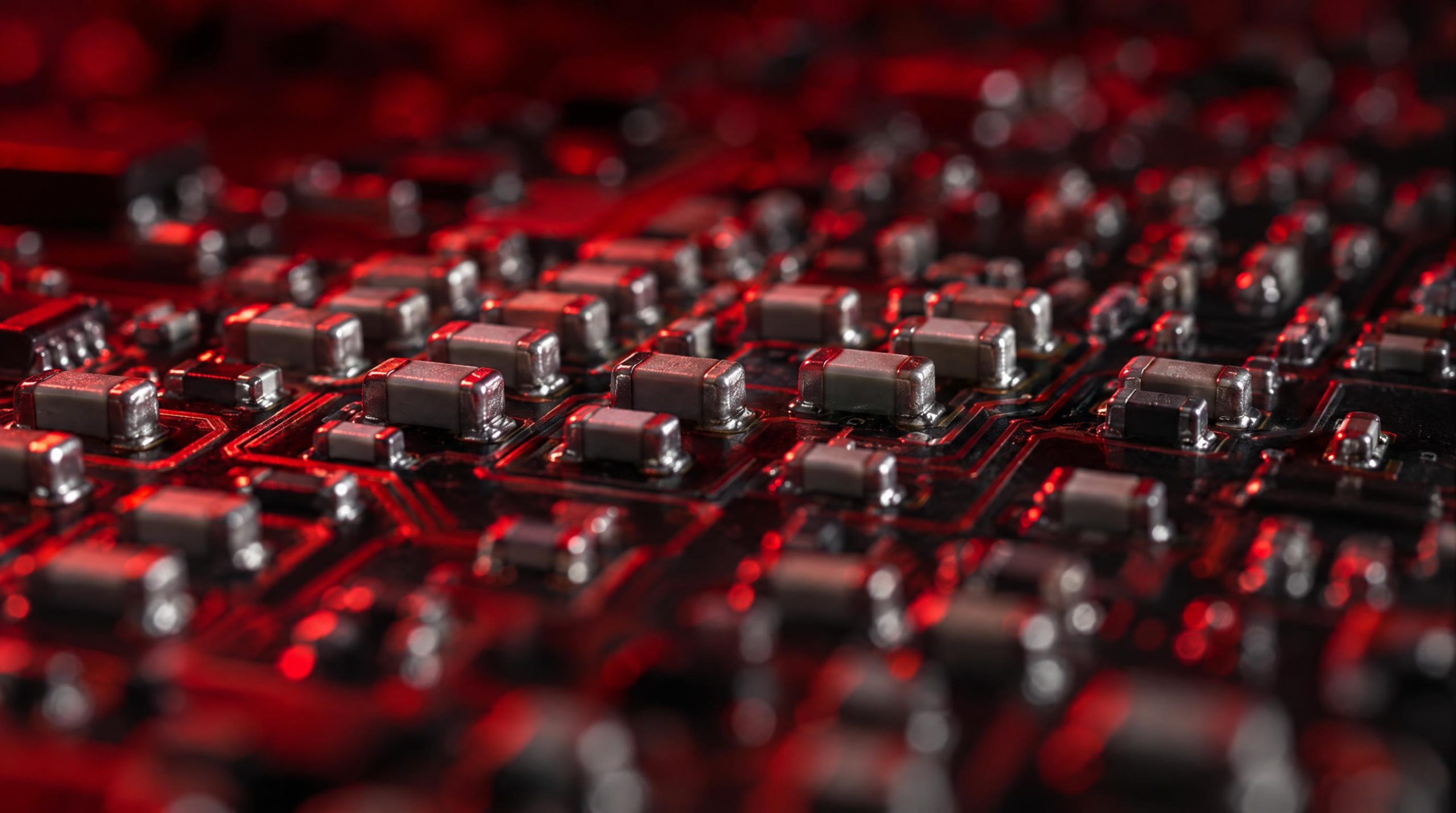
Open any modern PCB and the smallest rectangular chips soldered across the board in their hundreds — sometimes thousands — are almost certainly ceramic capacitors. Ceramic capacitors are the most widely produced passive component in electronics, yet the alphanumeric codes printed on their reels or listed in datasheets remain a persistent source of confusion. A part marked C0G and one marked X7R may share the same physical footprint and even the same nominal capacitance value, but they behave like different components under real operating conditions. Choose the wrong one and you may find a power rail oscillating, a filter corner drifting, or an RF circuit that refuses to tune.
This article explains how ceramic capacitors are classified, what the dielectric codes actually encode, and how that information translates into practical component selection. Whether you are laying out a PCB for the first time or reviewing a BOM for a new product revision, the goal is a clear, working mental model of ceramic capacitor types and when to use each.
Classes · Dielectric Codes · Practical Selection Guide
⚡ Core Principle: Two capacitors with identical footprint and nominal value can behave like entirely different components — the dielectric code tells you how they actually perform.
|
CLASS I
C0G / NP0
Best For: RF, oscillators, precision analog, timing
|
CLASS II
X7R / X5R
Best For: Decoupling, bypassing, filtering
|
|
CLASS III
Y5V / Z5U
⚠ Avoid in new designs
|
Each 3-character EIA code encodes a full temperature performance specification
|
X
Position 1
|
7
Position 2
|
R
Position 3
|
|
① Lower Temp Limit
X = −55°C
Y = −30°C Z = +10°C |
② Upper Temp Limit
4 = +65°C
5 = +85°C 7 = +125°C 8 = +150°C |
③ Max Cap. Drift
P = ±10%
R = ±15% S = ±22% V = +22% / −82% |
|
X7R −55°C to +125°C · max ±15% drift · industrial workhorse
|
X5R −55°C to +85°C · max ±15% drift · consumer default
|
Y5V −30°C to +85°C · up to −82% drift · avoid
|
|
A 10 µF X7R capacitor rated at 16 V can behave like only 2 µF when 12 V is applied. Some datasheets show derating of 70% or more at rated voltage. |
Illustrative: Capacitance Loss (curves vary by part)
0V bias (nominal) 100%
50% rated voltage ~55%
75% rated voltage ~20%
Rule: Select voltage rating ≥ 2× operating voltage
|
|
RF & Oscillators
Frequency-setting, impedance-matching, clock circuits
C0G / NP0
|
Precision Analog & Timing
Filters, measurement, timing constants, DAC outputs
C0G / NP0
|
|
MCU / FPGA Decoupling
Power pin bypass, digital supply filtering, industrial temp
X7R
|
Consumer Bulk Bypass
Mobile, wearables, indoor electronics below 85°C
X5R or X7R
|
|
Coupling / DC Blocking
Signal AC coupling where precision is not critical
X7R
|
Automotive / Industrial
ECUs, motor drives, ADAS — use AEC-Q200 rated parts
X7R / X8R AEC-Q200
|
|
2×
Voltage Derating
Minimum voltage rating vs. operating voltage for Class II
|
+30%
Aging Margin
Oversize capacitance on long-life products for X7R aging loss
|
∥
Parallel Values
Use 100 nF + 10 nF in parallel for broadband decoupling
|
|
C0G
For Stability
When value sets a circuit parameter — never use Class II
|
Noise Mitigation
Use flex-termination variants or C0G to stop audible buzz
|
|
1
|
The dielectric code — not the package size — determines real-world behavior. A 10 µF C0G and a 10 µF X7R are functionally different components under operating conditions. |
|
2
|
Use C0G when capacitance sets a circuit parameter. RF circuits, oscillators, filters, and timing circuits require the near-zero drift that only Class I delivers. |
|
3
|
X7R DC bias derating is your biggest hidden risk. Always check the manufacturer’s bias curve and derate voltage by at least 2× — your 10 µF cap may only deliver 2 µF in circuit. |
|
4
|
The 3-character EIA code gives you a complete temperature spec in 3 characters. Position 1 = lower temp limit · Position 2 = upper temp limit · Position 3 = max capacitance drift. |
|
5
|
Y5V and Z5U should not be used in new designs. With modern X7R delivering 22 µF+ in 0603, there is no justification for a dielectric that can lose 82% of its capacitance in normal operation. |
Need ceramic capacitors for your next build?
X7R · C0G · X5R · High-Voltage · AEC-Q200 · Current-production and hard-to-find values
WIN SOURCE · Global independent distributor of electronic components
What Is a Ceramic Capacitor?
A ceramic capacitor is a fixed-value capacitor in which the dielectric — the insulating material between the electrodes — is a ceramic compound. In the multilayer ceramic capacitor (MLCC) form factor that dominates modern design, this means alternating thin sheets of ceramic material and metal electrodes are stacked and co-fired into a single monolithic chip. More layers and thinner dielectric sheets allow higher capacitance in less space, which is why a 10 µF capacitor today can fit in a package smaller than a grain of rice.
The ceramic material is not merely structural. The composition of the ceramic defines the electrical behavior of the capacitor — its dielectric constant, its loss factor, and critically, how stable its capacitance remains as temperature, voltage, and time vary. This is why ceramic capacitor selection always begins with the dielectric type, not just the capacitance value and voltage rating. A capacitor that reads 10 µF on the reel may deliver only a fraction of that once it is installed on a board and placed under operating voltage.
Ceramic capacitors are non-polarized, which means they can be placed in either orientation in a circuit without concern for polarity — a practical advantage over electrolytic and tantalum types. Their very low equivalent series resistance (ESR) and equivalent series inductance (ESL) also make them well-suited for high-frequency work, where electrolytics lose effectiveness.
Ceramic Capacitor Classes: Class I, II, and III
Industry bodies including the IEC (International Electrotechnical Commission) and the EIA (Electronic Industries Alliance) have defined application classes for ceramic dielectrics based on how capacitance changes with temperature, voltage, and time. These classes provide engineers with a consistent framework for comparing and selecting parts across manufacturers.
Class I dielectrics are temperature-compensating, paraelectric materials engineered for predictability. They deliver excellent stability, very low loss, and essentially no aging, but only modest capacitance density — so values stay in the picofarad to low-nanofarad range. C0G (NP0) is the dominant Class I dielectric in production today.
Class II dielectrics are based on high-permittivity, ferroelectric barium-titanate ceramics. They pack far more capacitance into the same case size, which is how you get microfarads in an 0603 package. The trade-off is that their capacitance drifts with temperature and applied voltage, they age over time, and the ferroelectric structure introduces a piezoelectric effect. X7R and X5R are the most commonly specified Class II dielectrics.
Class III dielectrics push density further at the cost of still poorer stability. Y5V and Z5U are the familiar examples. Note that classification can differ between standards: under EIA RS-198, Y5V and Z5U are grouped as high-K Class II dielectrics, while IEC 60384 and many published references treat the same materials as Class III. In practical terms, the distinction matters less than understanding their behavior: Class III types are largely obsolete in modern SMD design and should generally be avoided in new layouts.
Reading the Dielectric Codes
The three-character EIA code used for Class II and Class III dielectrics — the format seen in designations like X7R, X5R, and Y5V — encodes a temperature performance specification in three positions.
- First character (letter): the lower operating temperature limit. X = –55°C; Y = –30°C; Z = +10°C.
- Second character (digit): the upper operating temperature limit. 4 = +65°C; 5 = +85°C; 6 = +105°C; 7 = +125°C; 8 = +150°C.
- Third character (letter): the maximum allowed capacitance change across that range. P = ±10%; R = ±15%; S = ±22%; T = +22%/–33%; U = +22%/–56%; V = +22%/–82%.
So X7R means: operable from –55°C to +125°C, with a maximum capacitance shift of ±15% across that range. Y5V means: operable from –30°C to +85°C, with capacitance allowed to swing from +22% to –82% — a specification that reflects how dramatically that dielectric drifts near its edges.
Class I dielectrics use a different, older coding system based on temperature coefficient rather than a tolerance band. C0G encodes a temperature coefficient of 0 ±30 ppm/°C, which translates to less than ±0.3% capacitance change across the full –55°C to +125°C range — stable enough for precision analog and RF work.
Class I in Depth: C0G (NP0)
C0G is the modern EIA designation; NP0 (Negative-Positive-Zero) is the older naming convention for the same dielectric, still used in military and European standards. Both refer to identical materials — the “0” in each case is the numeral zero, not the letter O. The IEC 60384 equivalent designation is CG.
The defining properties of C0G are its three near-zeroes: near-zero temperature coefficient, near-zero voltage dependence, and near-zero aging rate. What you read on the datasheet is what you get in the circuit. There is no DC bias derating curve to consult, no aging budget to add to the BOM, and no piezoelectric noise to worry about. This makes C0G the default choice whenever the capacitance value directly sets a circuit parameter — a filter corner frequency, a timing constant, an oscillator frequency, an impedance-matching network in RF design.
The limitation is volumetric efficiency. Class I dielectrics use lower dielectric-constant ceramics, so they are physically larger for a given capacitance value. Practically speaking, you will rarely find C0G parts much larger than 100 nF to 470 nF without moving to much bigger and more expensive package sizes. For most bypass and bulk decoupling tasks that need microfarads of capacitance, C0G is not a practical option.
Class II in Depth: X7R — and Its Hidden Traps
X7R is the workhorse of digital and power-supply decoupling. Its barium titanate dielectric has a dielectric constant one to two orders of magnitude higher than Class I materials, which is what enables microfarads of capacitance in a tiny chip. For most MCU decoupling, power rail bypassing, and general-purpose filtering across the full industrial temperature range (–55°C to +125°C), X7R is the practical default.
That said, X7R carries three behaviors that datasheets understate and that have caused real-world circuit failures:
- DC bias derating: When a DC voltage is applied across an X7R capacitor, the ferroelectric dipoles in the barium titanate align with the electric field, reducing effective permittivity — and therefore capacitance. A 10 µF X7R capacitor rated at 16 V can behave like a 2 µF capacitor when 12 V is applied across it. Some manufacturers’ datasheets show derating curves that drop 70% or more at rated voltage. Always consult the specific manufacturer’s DC bias curve, and consider selecting a voltage rating at least twice the operating voltage to stay on the flatter portion of the curve.
- Aging: Ferroelectric domains in Class II dielectrics gradually realign over time in a process that causes a logarithmic decrease in capacitance. X7R typically loses approximately 1–2% per time decade (measured from the last firing). This means a freshly manufactured capacitor will have measurably less capacitance after years in service. Designers working on long-life products should add a margin of 20–30% over the nominal capacitance value required.
- Piezoelectric effect (microphonics): Because Class II dielectrics are ferroelectric, they are also piezoelectric. Board vibrations — from fans, motors, or speakers — can physically flex the capacitor, generating a small but measurable voltage. Conversely, AC ripple current can cause the capacitor to vibrate audibly. In audio circuits or low-noise analog designs, this is a genuine nuisance; in high-vibration industrial or automotive environments, it can be a reliability issue.
None of these behaviors disqualify X7R for its intended applications. They are design constraints that must be accounted for, not defects. For power supply decoupling, coupling, and high-density filtering where temperature stability requirements are modest, X7R remains the correct choice for the vast majority of designs.
Other Class II Dielectrics: X5R, Y5V, and Z5U
X5R covers –55°C to +85°C with the same ±15% capacitance tolerance as X7R. It offers comparable volumetric efficiency and often lower cost, making it a reasonable choice for consumer products that will never exceed 80°C in normal operation. X5R suffers the same DC bias derating and aging characteristics as X7R — the only meaningful difference is the reduced upper temperature limit. For designs that need to meet automotive or full industrial temperature grades, X7R is the appropriate choice; for a consumer device or mobile product operating in a controlled indoor environment, X5R is often adequate and cost-effective.
Y5V and Z5U offer the highest capacitance density of any ceramic dielectric, but at the cost of extreme instability. A Y5V capacitor’s capacitance is allowed to vary from +22% to –82% over its operating range — which means at temperature extremes or under voltage, it may deliver less than 20% of its nominal value. These materials were relevant in an era when high capacitance density was otherwise unachievable in ceramic packages. With modern X7R formulations routinely delivering 22 µF or more in an 0603 package, Y5V and Z5U have largely been displaced in new designs and should not be selected for any application where the capacitance value matters.
Application Guide: Matching Dielectric to Circuit
The right dielectric is determined by what the capacitor is doing in the circuit and what the operating environment demands. The following is a practical mapping of common applications to appropriate dielectric types:
- RF and oscillator circuits, frequency-setting networks: Use C0G (NP0). When the capacitance value directly determines a frequency, a filter corner, or an impedance match, zero drift and zero voltage dependence are mandatory. No Class II dielectric qualifies for this role.
- Precision analog, timing circuits, measurement equipment: Use C0G (NP0). Any application where capacitance drift with temperature or voltage would affect accuracy or timing belongs in Class I.
- Power supply decoupling and bypass (microcontrollers, FPGAs, ASICs): Use X7R. It provides stable bypass capacitance across the full industrial temperature range, and after proper voltage derating, it performs reliably in the vast majority of digital decoupling scenarios.
- Bulk filtering and high-density bypassing in consumer products: X5R or X7R depending on the operating temperature range. X5R offers more capacitance per package in applications that stay below 85°C.
- Coupling and DC blocking: X7R is the standard choice. Precision is rarely critical in coupling applications, and X7R’s density advantage matters here.
- Automotive and industrial electronics (engine control units, motor drives, ADAS): X7R rated for AEC-Q200, or high-temperature grades such as X8R, are required. Always apply aggressive voltage derating and consult DC bias curves for the specific part and operating conditions.
- Snubber circuits and high-voltage applications: Specialized high-voltage ceramic capacitors, often Class I, are used in power electronics snubbers and EMI suppression.
Smartphones and other consumer devices are illustrative of how different dielectrics coexist in a single product. A typical smartphone contains hundreds to thousands of ceramic capacitors: C0G parts in the RF front-end and clock circuits, X7R parts for decoupling the application processor and power management ICs, and X5R parts for bulk bypassing where temperature demands are lower.
Practical Derating and Design Rules
A few rules of thumb help translate dielectric knowledge into robust designs:
- Voltage derating for Class II: Select a voltage rating at least twice the operating voltage to keep the capacitor in the flat region of its DC bias curve. In automotive and high-reliability designs, 3x to 4x derating is not uncommon.
- Aging margin for Class II: For long-life products, oversize the capacitance by 20–30% to account for aging over the product lifetime. A ten-year product spanning roughly four time decades can expect around 10% capacitance loss from aging alone, compounded by DC bias effects.
- Parallel placement for broadband decoupling: No single capacitor value has low impedance across all frequencies. Placing capacitors of different values in parallel — for example, a 100 nF and a 10 nF beside each processor power pin — keeps impedance low across a wider frequency band.
- C0G for stability, not for bulk: If you need stable capacitance but the required value exceeds what C0G offers in a reasonable package size, consider whether a film capacitor might be the more appropriate technology.
- Audible noise mitigation: If X7R or X5R capacitors are audibly buzzing in a power converter running at audio frequencies, consider switching to C0G where feasible, using soft-termination (flex-termination) variants, or moving to a switching frequency outside the audible band.
Sourcing Ceramic Capacitors
MLCC supply has historically been volatile. Demand spikes from automotive electrification, 5G rollouts, and consumer electronics manufacturing have created significant shortages for specific dielectric types and package sizes, particularly X7R in small case sizes (0402 and 0201). Lead times that are typically weeks can extend to many months during shortage events, and commodity pricing for MLCCs can shift substantially within a single quarter.
For design teams, the practical implication is that dielectric and manufacturer selection should include a consideration of supply availability — not just electrical performance. Confirming second-source options during the design phase, and maintaining some buffer stock for high-volume parts, reduces production risk. BOM reviews should also flag any MLCC line items that have a single-source dependency or that rely on an aging product family that may approach end-of-life status.
WIN SOURCE, a global independent distributor of electronic components, stocks ceramic capacitors across a broad range of dielectric types, case sizes and voltage ratings, covering current-production parts as well as values that are hard to find, and supports shortage sourcing, lifecycle management and alternative component solutions — engaged as a supply-chain partner before a shortage becomes a production stoppage, not after. Any substitute dielectric or package proposed for an existing design should be approved by your own engineering team, since a matching capacitance and footprint does not guarantee matching DC-bias, aging and temperature behavior.
Summary
Ceramic capacitors are not interchangeable by value and package size alone. The dielectric class determines how a capacitor actually behaves in your circuit: C0G (NP0) gives you the stability and precision that RF, timing, and analog circuits demand, while X7R and X5R offer the capacitance density that power-supply decoupling and digital bypassing require — provided you account for DC bias derating, aging, and the piezoelectric effect in your design margins. Y5V and Z5U remain available but offer so little reliable capacitance across real operating conditions that they are difficult to justify in any new design.
The EIA three-character code on a Class II MLCC encodes a complete picture of its temperature performance: lower temperature limit, upper temperature limit, and maximum allowable drift. Reading that code correctly takes the guesswork out of initial part selection. The datasheet’s DC bias curve does the rest. Apply both, design in margin, and ceramic capacitors will be reliable, cost-effective components in virtually any electronic application.
Frequently Asked Questions
What does X7R mean on a ceramic capacitor?
X7R is an EIA temperature-characteristic code for a Class II dielectric. The X means the lower operating limit is –55°C, the 7 means the upper limit is +125°C, and the R means capacitance may change by up to ±15% across that range. The code says nothing about DC bias derating or aging, both of which affect X7R parts and must be read from the manufacturer’s datasheet.
Is C0G the same as NP0?
Yes. C0G is the EIA designation and NP0 (negative-positive-zero) is the older name for the same Class I dielectric, still common in military and European documentation; the IEC 60384 designation is CG. In each case the character is the numeral zero, not the letter O. The dielectric has a temperature coefficient of 0 ±30 ppm/°C, essentially no voltage dependence and no aging, which is why it is specified wherever the capacitance value sets a circuit parameter.
Why does a 10 µF MLCC measure much less than 10 µF in the circuit?
Because Class II dielectrics such as X7R and X5R lose capacitance when a DC voltage is applied across them. The ferroelectric barium-titanate ceramic polarizes under the field, and the effective capacitance can fall by more than half at a substantial fraction of the rated voltage, with small case sizes affected most. The datasheet’s DC bias curve is the only reliable guide; selecting a voltage rating of at least twice the operating voltage keeps the part on the flatter part of that curve.
Can I substitute an X5R capacitor for an X7R?
Electrically they behave alike below 85°C: both are ±15% Class II dielectrics with similar DC bias and aging characteristics. The difference is the upper temperature limit, +85°C for X5R against +125°C for X7R, so the substitution is only acceptable when the application never approaches 85°C. For automotive, industrial or any full-temperature-range design, keep X7R and check the specific part’s bias curve, and route the substitution through your engineering team’s approval.
Are Y5V and Z5U capacitors still used?
They are still manufactured but are difficult to justify in a new design. Y5V allows capacitance to swing from +22% to –82% across –30°C to +85°C, so the part may deliver a small fraction of its nominal value at temperature extremes or under bias. Modern X7R and X5R formulations reach the capacitance densities that once required Y5V or Z5U, with far more predictable behavior, so those dielectrics are mainly encountered when supporting older designs.
Part discontinued, obsolete or hard to find?
WIN SOURCE is a global independent distributor of electronic components, supporting component supply, shortage sourcing, lifecycle management and alternative solutions. Visual inspection, non-destructive testing and electrical testing are applied according to material risk, customer requirements and the applicable quality process, and orders are covered by the published return policy and a 3-year warranty on eligible components.
Stock and pricing are updated daily — search a part number or contact us for current availability, lead time and a quote.
© 2026 Win Source Electronics. All rights reserved. This content is protected by copyright and may not be reproduced, distributed, transmitted, cached, or otherwise used without the prior written permission of Win Source Electronics.
