
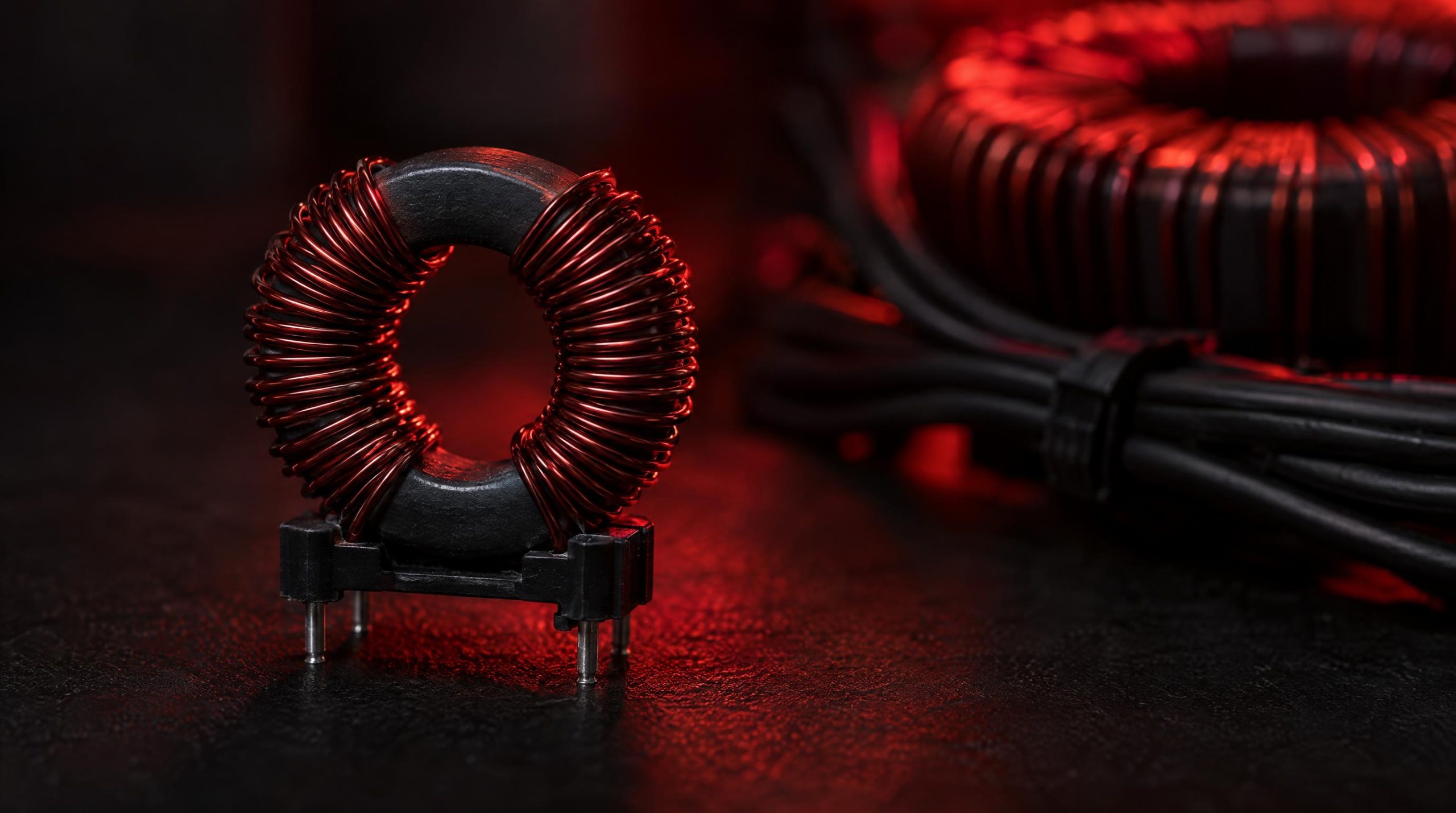
Electromagnetic interference is a persistent challenge in modern electronic design. As switching frequencies climb, data rates increase, and more subsystems share the same board or cable harness, the opportunities for noise to corrupt signals or push a product out of regulatory compliance multiply accordingly. The common mode choke is one of the most reliable and cost-effective tools available to designers for controlling that noise — specifically the kind that appears simultaneously on both conductors of a line and travels referenced to ground.
This article covers how common mode chokes work, how they are built, what the key specifications actually mean in practice, where they are used, and — critically — how to pick the right one for a given application. It also addresses PCB layout considerations that are often overlooked but can make or break filter performance. Whether you are designing an AC power entry filter, a USB interface, an Ethernet port, or an automotive control line, the fundamentals here apply.
How they work, why they matter, and how to select the right one for your design — a visual technical reference.
|
4
Choke Types
|
6
Key Specs
|
|
8
Selection Steps
|
∞
Applications
|
|
What a Common Mode Choke Does
|
|
Blocks
Common Mode Noise
Currents flowing in the same direction on both conductors — present high impedance
|
✅
Passes
Differential Signal
Opposing-direction currents — fluxes cancel, nearly zero impedance to useful signal
|
|
⚡
Mechanism
Magnetic Flux
Both windings share one core — differential flux cancels, common mode flux adds
|
Purpose
EMI Compliance
Reduces conducted emissions per CISPR 32, FCC Part 15, IEC 61000 standards
|
|
The Operating Principle
|
|
1
Shared Core
Two matched windings wound symmetrically on one ferrite core
|
2
Differential Mode
Opposing currents → fluxes cancel → near-zero inductance → signal passes freely
|
|
3
Common Mode
Same-direction currents → fluxes add → high impedance → noise is suppressed
|
4
Above SRF
Parasitic capacitance dominates → impedance falls → always select SRF above noise band
|
|
Core Materials & Frequency Range
|
|
MnZn Ferrite
Manganese-Zinc — high permeability, low-frequency specialist
~1 kHz – a few MHz
Best for: Power line filtering
|
NiZn Ferrite
Nickel-Zinc — lower permeability, high-frequency performer
~1 MHz – 500+ MHz
Best for: Signal & data line chokes
|
Nanocrystalline
Amorphous/nanocrystalline — high permeability AND high-frequency
Wide spectrum
Best for: Demanding dual-range applications
|
|
4 Types of Common Mode Chokes
|
|
Toroidal Through-Hole
AC Mains Filtering
1 mH–30 mH, rated to 30 A+. Dominant for line-voltage equipment.
|
SMD Signal-Line
USB / HDMI / Ethernet
90 nH–few µH. Priority: low differential insertion loss, controlled impedance.
|
|
⚙️
SMD Power-Line
DC-DC / Motor Drive
Compact for auto assembly yet rated for supply currents in computing & telecom.
|
Multi-Line
3-Phase / Multi-Lane
3+ conductors on one core. Winding symmetry critical to prevent crosstalk.
|
|
6 Key Specifications Explained
|
|
|
|
|
|
|
|
8-Step Selection Process
|
|
1
|
Define the application — Power or signal line? AC mains or DC bus? Sets which specs matter most.
|
|
2
|
Identify the target frequency band — Mains: 150 kHz–30 MHz. USB 2.0: ~100–300 MHz. USB 3.x/HDMI: multi-GHz.
|
|
3
|
Determine current requirement — Apply 20–30% derating margin below rated max for temperature and load variation.
|
|
4
|
Check impedance & insertion loss curves — Verify impedance at actual noise frequency, not just the datasheet reference point.
|
|
5
|
Evaluate leakage inductance — For high-speed diff pairs: verify differential insertion loss stays within link budget across the data rate.
|
|
6
|
Confirm DCR & thermal budget — Calculate I² × DCR power dissipation. Ensure temperature rise is within component and PCB ratings.
|
|
7
|
Select package & mounting style — SMD for compact auto-assembly; through-hole wound for power line current handling.
|
|
8
|
Verify environmental & qualification requirements — Automotive: AEC-Q200. High-temp: check Curie temperature. Safety: UL/VDE/CSA approvals as required.
|
|
Critical PCB Placement Rules
|
|
Position
Place as close as possible to the connector — within a few mm for high-speed lines. Any trace before the choke acts as an unfiltered antenna.
|
⚖️ Symmetry
Match trace length, width, and spacing into and out of the choke. Asymmetric routing converts differential signals into common mode noise.
|
|
Thermal
Adequate copper pads and thermal vias for high-current parts. Keep power-line chokes away from temperature-sensitive analog circuitry.
|
Pair with Y-Caps
Choke + Y capacitors (IEC 60384-14 rated) = substantially better suppression. The cap provides a low-impedance return path for CM noise current.
|
|
Where Common Mode Chokes Are Used
|
|
AC Mains Entry
First filter after fuse
|
USB / HDMI
Near connector on PCB
|
Ethernet / CAN
Data interface lines
|
|
Automotive
AEC-Q200, −40–125°C
|
⚕️
Medical / Industrial
Safety-critical EMC
|
☀️
Solar / EV Charging
High-freq + long cables
|
|
5 Key Takeaways
|
|
✓
|
Match the impedance curve to the noise band — single-point specs are not enough. The choke’s impedance peak must align with the actual problem frequency range.
|
|
✓
|
Keep leakage inductance low for high-speed interfaces — excess LLK degrades eye diagrams. Look for ultra-low leakage series for USB 3.x, HDMI, and DisplayPort.
|
|
✓
|
PCB placement is as important as component selection — place the choke within millimeters of the connector, maintain routing symmetry, and pair with properly rated Y capacitors.
|
|
✓
|
Derate current rating by 20–30% — temperature and load variation reduce effective headroom. Verify I² × DCR thermal budget against the component’s rated operating range.
|
|
✓
|
Qualify alternates early in the design phase — popular series targeting USB, HDMI, and automotive CAN can go on allocation. A specification-matched alternate avoids forced board redesigns.
|
|
WIN SOURCE
Global Electronic Components Distributor — Common Mode Chokes & EMI Filters
|
win-source.net
|
What Is a Common Mode Choke?
A common mode choke is a passive, two-winding magnetic component wired in series with a conductor pair. Its job is to present high impedance to currents that flow in the same direction on both conductors simultaneously (common mode) while presenting very low impedance to currents that flow in opposite directions (differential mode, which carries the actual signal or load current). The result is a component that can substantially attenuate conducted EMI without loading the circuit it protects. It is a standard building block of EMI filters found in everything from AC mains entry modules to high-speed USB and Ethernet interfaces.
Understanding Common Mode Noise
To appreciate why a common mode choke is useful, it helps to understand what common mode noise actually is. In any two-conductor system (a power line pair, a differential data pair, a motor drive output), there are two distinct types of noise current. Differential mode noise flows in one conductor and returns in the other — it is effectively in series with the load and tends to stay contained within the loop formed by the two conductors. Common mode noise, by contrast, flows in the same direction on both conductors and returns through the ground reference or chassis. Because it uses the earth or chassis as its return path, common mode noise is particularly prone to radiation and to coupling into other circuits.
In practice, switching power supplies, motor drives, fast digital interfaces, and long cable runs are all significant sources of common mode noise. Regulatory standards such as CISPR 32, FCC Part 15, and the IEC 61000 series set limits on conducted and radiated emissions that ultimately trace back to these noise mechanisms. The common mode choke addresses the problem directly at the source or at the boundary of a subsystem, before the noise can propagate along cables or back onto the supply rail.
How a Common Mode Choke Works
The operating principle relies on magnetic flux behavior inside a shared core. Both conductors are wound around the same magnetic core, and the winding orientation is chosen so that differential-mode currents — which flow in opposite directions — produce magnetic fluxes that cancel almost entirely within the core. Because the net flux is near zero, the core presents essentially no inductance to normal operating (differential) current, and the load current passes through with only the small resistive drop of the winding wire itself.
When common mode noise is present, both conductors carry current flowing in the same direction. The resulting magnetic fluxes now add together inside the core rather than canceling. The component behaves as a high-impedance inductor at the noise frequency, opposing the noise current and reducing the amplitude that propagates further into the system. This impedance is frequency-dependent: it rises with frequency up to the component’s self-resonant frequency (SRF), above which parasitic capacitance dominates and impedance begins to fall. This frequency dependence is what makes matching a choke to the right frequency band so important in practice.
Construction and Core Materials
A common mode choke consists of a magnetic core with two matched windings wound symmetrically, one for each conductor of the pair. The windings are typically insulated copper wire, and winding symmetry matters: any imbalance between the two windings creates leakage inductance, which adds differential-mode impedance and can degrade signal integrity on high-speed lines. The core is most commonly a ferrite material, chosen for its high magnetic permeability and relatively low core loss at the frequencies where EMI suppression is needed.
Core material selection has a direct effect on the usable frequency range. Manganese-zinc (MnZn) ferrites offer high permeability and are effective from the low kilohertz range up to a few megahertz — well suited for power line filtering. Nickel-zinc (NiZn) ferrites have lower permeability but remain effective to higher frequencies, typically from a few megahertz up to several hundred megahertz, which makes them the preferred choice for signal and data line chokes. Some designs use nanocrystalline or amorphous metal cores when both high permeability and high-frequency performance are needed simultaneously — a combination that is otherwise difficult to achieve with standard ferrite materials.
The physical form factor of the core also matters. Toroidal cores contain magnetic flux efficiently within the ring shape, which minimizes radiation from the choke itself and generally allows for higher inductance in a given volume. Drum or pot cores are used in surface-mount constructions where the compact profile is more important than ultimate inductance. Larger through-hole wound chokes on toroidal cores dominate the power line market, while multi-layer ceramic constructions (similar to a ceramic capacitor in form) are used for miniature SMD signal-line chokes rated for GHz-range operation.
Types of Common Mode Chokes
Common mode chokes are generally categorized by their construction and intended application, and the distinction matters for selection purposes because a power-line choke and a data-line choke share the same operating principle but are optimized for very different environments.
Toroidal through-hole chokes are the dominant choice for AC mains filtering. They are wound on a ferrite or iron-powder toroidal core and are typically rated for continuous currents from a few amperes up to 30 A or more, with common mode inductance values in the range of 1 mH to 30 mH. Their larger physical size supports the higher current ratings and voltage insulation requirements of line-voltage equipment.
Surface-mount (SMD) signal-line chokes are designed for data interfaces such as USB, HDMI, DisplayPort, Ethernet, and CAN bus. These are available in compact ceramic or wound packages with footprints as small as 0402. The priority here is low differential-mode insertion loss and controlled impedance across the signal bandwidth, not high current capacity. Inductance values are lower (typically 90 nH to a few microhenries), but the target noise frequencies are much higher.
SMD power-line chokes bridge the gap between the two categories — compact enough for automated PCB assembly but rated for the currents common in DC-DC converter inputs or motor drive outputs. These are common in telecommunications and computing equipment where board space is tight but supply filtering is required.
Multi-line chokes wind three or more conductors on a single core and are used where multiple lines must be filtered together, such as three-phase power inputs or multi-lane high-speed interfaces. Winding symmetry becomes even more critical in multi-line designs to avoid inter-winding crosstalk.
Key Specifications to Understand
Reading a common mode choke datasheet effectively requires understanding which specifications matter for a given application. Several parameters appear on all datasheets; not all are equally important for every design.
Common mode inductance (LCM) is the inductance measured when both windings are driven in phase. It is the primary indicator of low-frequency noise suppression capability — higher inductance means more impedance at a given low frequency. For power line chokes, this is typically the headline specification.
Common mode impedance (ZCM) vs. frequency is arguably more useful than the inductance value alone. Impedance depends on both the inductive reactance and the core’s loss characteristics and, for this reason, is usually plotted as a curve. The impedance value at the specific frequency where noise is a problem — not at an arbitrary reference frequency — is what determines how effective the choke will be. Manufacturers typically publish impedance at 100 MHz for signal-line chokes and at lower frequencies for power-line chokes.
Self-resonant frequency (SRF) is the frequency at which parasitic capacitance between the windings resonates with the winding inductance. Above the SRF, the component becomes capacitive and impedance falls with increasing frequency. For practical noise suppression, the target noise band must sit comfortably below the SRF. Signal-line chokes for USB 3.x or HDMI must have SRFs well above the fundamental data frequency, which puts requirements on very low parasitic capacitance and, in turn, on winding geometry.
Leakage inductance (LLK) is the differential-mode inductance that results from imperfect flux coupling between the two windings. It is desirable to keep this low for signal line applications because it adds series inductance to the differential signal path and can cause insertion loss, impedance mismatch, and eye diagram degradation in high-speed links. Many manufacturers of high-speed interface chokes explicitly rate leakage inductance and offer “ultra-low leakage” series for critical applications.
Rated current and DC resistance (DCR) define the thermal behavior of the choke under load. For power-line chokes, the rated current must exceed the maximum continuous operating current of the circuit. Exceeding the current rating can cause core saturation (in gapped designs) or thermal runaway, both of which degrade noise suppression. DCR contributes directly to I²R heating and to power loss in efficiency-sensitive applications.
Insertion loss is the most direct measure of filter performance: it quantifies how much the choke attenuates a signal at a given frequency, expressed in decibels. Where available, insertion loss curves are preferable to single-point impedance values because they capture the full frequency behavior, including the roll-off above SRF.
Common Mode Choke vs. Differential Mode Choke
Common mode and differential mode noise require fundamentally different filter structures, and confusing the two leads to ineffective designs. A common mode choke suppresses equal-phase noise that appears identically on both conductors relative to ground; it does not attenuate noise that exists as a voltage difference between the two conductors. A differential mode choke (or a simple series inductor) addresses line-to-line noise directly but has no specific effect on common mode noise.
In practice, most real-world EMI problems involve a mixture of both types, which is why AC mains filter circuits typically combine a common mode choke (for common mode suppression) with X capacitors (which short differential-mode noise across the line) and Y capacitors (which divert common mode noise to ground). The common mode choke in such a circuit sees the full load current in differential mode, where its flux cancellation ensures that core saturation is not an issue. The complementary capacitors handle the noise components that the choke cannot address on its own.
Where Common Mode Chokes Are Used
Common mode chokes appear at virtually every electromagnetic boundary in electronic equipment. At the AC mains input, they are the first active filter element after the fuse, reducing conducted emissions both outward (preventing the equipment from disturbing the power grid) and inward (protecting the equipment from line-borne disturbances). In switching power supplies and motor drives, they appear at both input and output stages to contain the high-frequency harmonics generated by the switching elements.
On data and interface lines, common mode chokes are placed close to connectors on USB, HDMI, DisplayPort, Ethernet, CAN, LIN, and FlexRay interfaces. The function here is to prevent cable-borne common mode currents from radiating as antennas or from conducting noise back into sensitive analog front ends. Automotive designs add the requirement for AEC-Q200 qualification and a wider operating temperature range, typically −40 °C to +125 °C or beyond.
Medical instrumentation, industrial automation, and telecommunications equipment all rely heavily on common mode chokes because the cost of EMI-related malfunction in those environments is high. In medical devices, for instance, stable low-noise electrical performance is required not only for regulatory compliance but for patient safety. Industrial motor drives create some of the harshest conducted EMI environments encountered in practice, and multi-stage filter designs using common mode chokes are standard in those products.
The component also appears in less obvious places: on the power lines of audio amplifiers to suppress switching noise from Class D stages; on IoT radio modules to reduce coexistence problems between different wireless protocols sharing the same product; and in solar inverters and EV charging systems, where the combination of high switching frequencies and long cable runs creates significant common mode currents that can interfere with grid communications equipment.
PCB Placement and Layout Considerations
Component selection and PCB placement are equally important — a well-chosen choke placed poorly will underperform significantly. The most fundamental rule is to position the choke as close as possible to the connector or to the point where the cable enters the board, ideally within a few millimeters for high-speed signal lines. Any trace length between the connector and the choke acts as an unfiltered antenna that can radiate noise or pick up interference before the filter element is encountered.
Routing symmetry is critical for differential pair interfaces. The two traces entering and leaving the choke must be matched in length, width, and spacing. Asymmetric routing introduces a length or impedance mismatch between the two conductors, which converts some portion of the differential signal into common mode noise — precisely the opposite of the intended effect. For high-speed designs, maintaining the characteristic impedance of the differential pair through the choke footprint area also matters; stub lengths to the choke pads should be kept as short as practical.
On power lines, thermal management becomes an additional layout concern. The choke’s DCR causes resistive heating that scales with the square of the current. Adequate copper area on the pads and thermal vias under high-current through-hole parts help manage temperature rise and keep the component within its rated operating range. Placing power-line chokes away from temperature-sensitive analog circuitry is also advisable.
Finally, it is worth noting that a common mode choke in a power filter circuit is only half of the filter. Pairing it with appropriately rated Y capacitors (line-to-ground) to provide a low-impedance return path for the common mode noise current substantially improves suppression compared to the choke alone. The capacitor selection must respect the relevant safety standards (IEC 60384-14 for Y capacitors) because these components are directly across the mains voltage in many filter topologies.
How to Select the Right Common Mode Choke
Selecting a common mode choke is a multi-variable matching problem. No single specification defines the right part; the correct choice emerges from evaluating several parameters together against the demands of the specific application.
- Define the application context first. Power line or signal line? AC mains or DC bus? High-speed data interface or low-frequency control line? The application type determines which specifications matter most and sets the bounds on acceptable package sizes, current ratings, and environmental requirements.
- Identify the target frequency band. Determine where the problematic noise energy is concentrated. For conducted mains emissions, this is often in the 150 kHz to 30 MHz range. For USB 2.0 common mode noise, the troublesome band is typically 100 to 300 MHz. For USB 3.x or HDMI, it extends to several gigahertz. The choke’s impedance peak must align with this band, and the SRF must sit above it.
- Determine the current requirement. For power line chokes, identify the maximum continuous operating current and apply a derating margin — typically 20 to 30 percent below the rated maximum to account for temperature effects and load variations. For signal line chokes, current is rarely the limiting factor, but verify that the bias current from line terminations will not begin to affect core permeability.
- Check common mode impedance and insertion loss curves. Single-point impedance values at a standard frequency (such as 100 MHz) are a useful starting filter, but the impedance-versus-frequency curve from the manufacturer datasheet gives a much clearer picture. Confirm that the impedance is sufficient at the actual noise frequency, not just at the datasheet reference point.
- Evaluate leakage inductance for signal lines. For any high-speed differential interface, leakage inductance directly affects signal integrity. Request or calculate the leakage inductance value and verify through simulation or measurement that differential insertion loss stays within the link budget across the operating data rate.
- Confirm DCR and thermal budget. For higher-current applications, calculate the power dissipation (I² × DCR) and ensure the resulting temperature rise is compatible with the component’s rating and the thermal environment of the PCB. High DCR also means efficiency loss in power conversion applications.
- Select the package and mounting style. SMD packages suit compact PCBs and automated assembly processes. Through-hole wound chokes are the norm for power line filters where larger physical size and wire gauge are needed for current handling. Match the package not only to the current rating but to the PCB footprint constraints and assembly process.
- Verify environmental and qualification requirements. Automotive designs require AEC-Q200 qualification. High-temperature environments require checking the component’s Curie temperature to ensure the core material remains effective. For safety-critical applications, verify that the voltage rating exceeds the peak differential voltage across the windings, and check for any relevant agency approvals (UL, VDE, CSA) required by the end product.
Sourcing and Supply Chain Considerations
Common mode chokes are produced by a relatively concentrated group of manufacturers — TDK, Murata, Würth Elektronik, Bourns, Pulse Electronics, Coilcraft, and Laird are among the most widely specified — and certain popular series, particularly those targeting USB, HDMI, and automotive CAN interfaces, can be subject to supply constraints during periods of high demand. Designing with a primary part and identifying at least one qualified alternate early in the design phase reduces risk if a preferred part goes on allocation or reaches end-of-life.
For passive components like common mode chokes, the practical concerns around lifecycle management are real: a specific part number may be discontinued when a manufacturer refreshes its product family, leaving designs that have relied on that part for years suddenly facing a sourcing gap. Maintaining visibility into manufacturer product change notices (PCNs) and engaging with distributors who track lifecycle status proactively helps manage this risk. Common mode chokes and other filter components are a category where lifecycle transitions happen regularly, and WIN SOURCE, a global independent distributor of electronic components, stocks them across current-production and hard-to-find part numbers and supports shortage sourcing and lifecycle management for exactly this situation.
When a specific part is unavailable, the alternative is not necessarily to redesign around a completely different choke. In many cases, an electrically equivalent substitute from a different manufacturer — matched on common mode inductance, impedance curve, current rating, DCR, and package — can be qualified in the existing design with manageable engineering effort — with final approval of the substitute resting with the customer’s engineering team, since a matching inductance and footprint does not guarantee a matching impedance curve or leakage inductance. This is where a thorough component analysis and a reliable source for specification-matched alternative solutions matters. A structured approach to evaluating cross-references, combined with access to verified inventory across a number of supply channels, keeps production lines running without forcing premature board redesigns.
Summary
Common mode chokes are straightforward in principle but nuanced in practice. The physics — differential flux cancellation for normal current, combined flux buildup for common mode noise — is consistent across all applications. The challenge is in translating that principle into the right part selection for a specific frequency range, current level, signal bandwidth, package constraint, and environmental requirement. Getting the impedance curve right, keeping leakage inductance under control for high-speed interfaces, managing DCR in power circuits, and placing the component correctly on the PCB are all steps that determine whether the filter actually works in production hardware.
Pairing careful selection with a robust sourcing strategy — identifying alternates early, monitoring lifecycle status, and maintaining access to verified stock across a number of supply channels — rounds out a complete approach to working with this essential passive component.
Frequently Asked Questions
What does a common mode choke do?
It presents high impedance to noise currents that flow in the same direction on both conductors of a pair and return through ground or chassis, while letting the normal differential signal or load current pass with almost no impedance. Both windings share one core: differential currents produce fluxes that cancel, common mode currents produce fluxes that add, so only the noise sees the inductance.
What is the difference between a common mode choke and a differential mode choke?
A common mode choke only attenuates noise that appears identically on both conductors relative to ground; it does nothing to line-to-line noise. A differential mode choke, or a plain series inductor, addresses line-to-line noise but has no specific effect on common mode noise. Mains filters usually combine a common mode choke with X capacitors for differential noise and Y capacitors to return common mode noise to ground.
Which specification matters most when choosing a common mode choke?
The common mode impedance at the frequency where your noise actually is, read from the impedance-versus-frequency curve rather than a single reference-point figure, with the self-resonant frequency sitting above that band. For power lines, rated current and DCR come next; for high-speed data lines, leakage inductance matters because it adds series inductance to the signal path and degrades the eye diagram.
Where should a common mode choke be placed on the PCB?
As close as possible to the connector or the point where the cable enters the board, ideally within a few millimeters on high-speed lines, so there is no unfiltered trace acting as an antenna between the connector and the choke. Keep the two traces through the choke matched in length, width and spacing, and keep stubs to the pads short so the differential impedance is preserved.
Can I substitute a common mode choke from another manufacturer?
Often, if the replacement matches on common mode inductance, the impedance curve across your noise band, rated current, DCR, leakage inductance and package. Because two parts with the same headline inductance can have very different impedance curves and self-resonant frequencies, the substitute should be verified by measurement or simulation in the actual design and approved by your engineering team before it goes into production.
Part discontinued, obsolete or hard to find?
WIN SOURCE is a global independent distributor of electronic components, supporting component supply, shortage sourcing, lifecycle management and alternative solutions. Visual inspection, non-destructive testing and electrical testing are applied according to material risk, customer requirements and the applicable quality process, and orders are covered by the published return policy and a 3-year warranty on eligible components.
Stock and pricing are updated daily — search a part number or contact us for current availability, lead time and a quote.
© 2026 Win Source Electronics. All rights reserved. This content is protected by copyright and may not be reproduced, distributed, transmitted, cached, or otherwise used without the prior written permission of Win Source Electronics.
