
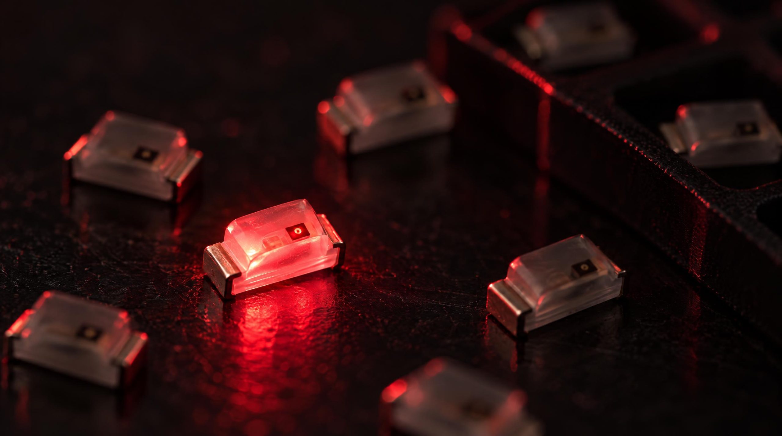
Discrete LED indicators are among the most straightforward components in electronics — a p-n junction, a lens, two leads — yet getting the procurement side wrong can quietly derail a production run or a long-running service contract. A specific shade of red that matched a legacy instrument panel, a 3 mm through-hole part that fits a mechanical enclosure drilled twenty years ago, a bin-matched batch needed to avoid visible color variation across a multi-unit assembly: these are real constraints, and they do not go away just because a manufacturer has moved on to a newer product family.
This article covers the full scope of working with discrete LED indicators: the selection parameters you need to evaluate before committing to a part, how LED binning works and what the codes on a datasheet actually mean, and what to do when the part you need is no longer in production. Whether you are specifying a new design or sustaining a legacy product, the goal is the same — consistent, reliable light output from parts you can actually source.
Selection parameters, LED binning decoded, and strategies for sourcing obsolete & EOL parts — all in one visual reference.
|
2–20 mA
Typical Drive Current
|
Not all
PCNs reach every buyer
|
|
12–18mo
Active → Obsolete
|
15–30yr
Product Service Life
|
|
Key Selection Parameters
|
|
Color & Wavelength
Dominant wavelength (nm) — not peak. Red: 620–645 nm · Green: 520–570 nm · Blue: 460–470 nm · Amber: 585–600 nm
|
Forward Voltage (Vf)
AlGaInP (red): ~1.8–2.2V · InGaN (blue/green): ~2.7–3.4V. Size resistors to maximum Vf, not typical.
|
Luminous Intensity
Measured in mcd on-axis at rated current. Only meaningful alongside viewing angle — wider angle = lower mcd at axis.
|
|
Package & Mounting
Through-hole: 3mm / 5mm / 8mm. SMD: 0402–1206, PLCC-2/4. Package drives PCB layout and assembly process.
|
Forward Current (If)
Std. continuous rating: 20 mA. Low-power designs: 5–10 mA (less bright). Never exceed absolute max — causes permanent damage.
|
| ▲ |
Selection Order: Evaluate wavelength first → then Vf & current → then package → then intensity & viewing angle. Skipping steps leads to subtle incompatibilities. |
|
LED Binning Explained
|
Wafer-level variation is physics, not defect. Binning sorts LEDs into matched groups so you get consistent output — critical when units appear side-by-side.
|
Wavelength Bins
Chips sorted into narrow nm windows after dicing. Controls perceived color consistency across all units.
|
Flux Bins
Luminous output grouped into ranges. Avoids visible brightness mismatches in multi-LED assemblies.
|
|
Voltage Bins
Vf matched for series-string circuits. A 0.2–0.3V mismatch can cause significant current imbalance.
|
Reading Bin Codes
No universal standard — each maker uses its own format. Always check the datasheet binning table, not just the part number.
|
| ⓘ |
Single-bin procurement ensures visual uniformity across a panel or array — request a specific bin code at order time and confirm the supplier can hold it consistent across repeat orders. |
|
Component Lifecycle Statuses
|
|
● Active
Full production. Available through standard distribution. Preferred status for new designs.
|
▲ NRND
Not Recommended for New Designs. Early warning — qualify an alternate now, while supply is available.
|
|
⚠ EOL
End of Life. Production stop announced. Last-time-buy window is open — act before it closes.
|
✖ Obsolete
No longer manufactured. Requires locating remaining stock across supply channels, or a qualified alternate part.
|
|
Sourcing Obsolete LED Indicators
|
Match package footprint, dominant wavelength, Vf range, and luminous intensity. Often a minor resistor tweak is all that’s needed. Pre-qualify alternates at design stage to avoid single-source risk.
|
For legacy, certified, or contractually-locked part numbers. Purchasable stock can still exist across a number of supply channels years after formal EOL — locating it is a sourcing exercise. LEDs have long shelf life when stored properly.
|
Obsolete parts = elevated counterfeit risk. Require: visual inspection, marking & date code check, functional Vf / luminous output test. Ask whoever is quoting about AS9120 / ISO 9001 certification, ERAI membership, traceability and inspection.
|
|
Proactive Supply-Chain Checklist
|
Need hard-to-find or EOL discrete LED indicators?
WIN SOURCE is a global independent distributor of electronic components, supporting component supply, shortage sourcing, lifecycle management and alternative solutions across the full component lifecycle.
AS9120 · ISO 9001 · ISO 14001 · ERAI Member
What Are Discrete LED Indicators?
A discrete LED indicator is a single light-emitting diode packaged for use as a status indicator on a printed circuit board or panel. These are the familiar components — a green dot that tells you a device is powered, a red flash that signals a fault, an amber blink on a network port — used across virtually every category of electronic equipment. Compared to LED arrays, backlight modules, or high-power illumination LEDs, indicator LEDs operate at low drive currents (typically 2–20 mA) and their primary job is visibility, not illumination. They are found in optoelectronics catalogs — usually under LED indication, discrete — alongside optocouplers and phototransistors, and they span both through-hole and surface-mount package families.
The category covers a wide range of products: standard 3 mm and 5 mm through-hole LEDs with domed or flat lenses, miniature SMD packages from 0402 up to 1206, PLCC-format surface-mount indicators with wide viewing angles, bi-color and tri-color parts with multiple dice in a single package, and flasher or cycling variants with integrated ICs. Despite being simple devices electrically, they have enough datasheet parameters to require careful evaluation before selection — and enough variation across manufacturers to make direct substitution non-trivial when an original part goes obsolete.
Key Selection Parameters
Discrete LED indicators are differentiated across several parameters on a datasheet: package type, wavelength or color, forward voltage, forward current, luminous intensity in millicandela, viewing angle, and mounting type. Understanding what each of these means in practice is the foundation of selecting the right part.
Color and Dominant Wavelength
For colored indicator LEDs, the relevant optical parameter is dominant wavelength, measured in nanometers (nm). This is not the same as peak wavelength — dominant wavelength is the single-wavelength equivalent that best represents how the human eye perceives the emitted color, accounting for the eye’s non-uniform spectral sensitivity. Red indicator LEDs typically fall in the 620–645 nm range, green in the 520–570 nm range depending on the chip chemistry, and blue in the 460–470 nm range. Amber and yellow parts occupy the 585–600 nm window. The choice of color in an indicator application usually follows convention — green for normal/active, red for fault or power-off, amber for warning — but in some industrial, medical, or aviation contexts the wavelength may need to hit a defined specification rather than just a general color family.
Forward Voltage and Forward Current
Forward voltage (Vf) and the material chemistry of the LED chip are linked at the physics level: the band gap of the semiconductor determines both the emission wavelength and the minimum voltage needed to inject carriers across the junction. Red LEDs built on AlGaInP material typically require around 1.8–2.2 V, while blue and green InGaN devices need 2.7–3.4 V. In practical indicator design, this matters because a current-limiting resistor calculated for a red LED will not work for a blue replacement without adjustment — the voltage drop across the LED is meaningfully different. Most indicator datasheets specify Vf at a test current (commonly 10 or 20 mA), and it is the maximum Vf that should drive resistor sizing, not the typical value, because LEDs run coolest — and therefore show highest Vf — at startup.
Forward current sets the brightness operating point. Standard indicator LEDs are rated for continuous operation at 20 mA, with absolute maximum ratings in the 30 mA range. Running an indicator at lower current (5–10 mA) is common in low-power designs; the tradeoff is reduced luminous output. For pulse-driven indicators, the peak current can be considerably higher, but the datasheet pulse-width and duty-cycle limits must be respected. Exceeding the maximum current causes irreversible degradation or immediate failure.
Luminous Intensity (mcd) and Viewing Angle
Luminous intensity, expressed in millicandela (mcd), is the brightness figure most often cited in indicator LED datasheets, but it is only meaningful when read alongside the viewing angle. A 5 mm LED with a 10° narrow lens can register 20,000 mcd, while a wide-angle SMD LED with the same total light output might show only 2,000 mcd on axis. The mcd figure is always measured on the optical axis at a specific forward current; off-axis brightness falls off according to the radiation pattern. For a direct-view indicator that a user looks at straight-on, a narrower angle and higher mcd rating works well. For a board-edge indicator viewed from the side, or for a part visible across a wide area, a wider viewing angle (120° or more) is the better choice even if the on-axis mcd number is lower. Bi-color PLCC indicators, for instance, are often specified with 120° viewing angles precisely because panel placement makes viewing angle critical.
Package and Mounting Type
Through-hole LED packages — 3 mm (T-1), 5 mm (T-1¾), and 8 mm — remain common in control panels, front-panel indicators, and any application where the LED must protrude above the board for visibility or mechanical fit. They have long leads, mount with high mechanical strength, and suit manual assembly or wave soldering. SMD packages offer the advantages of smaller footprint, lower profile, and compatibility with automated pick-and-place and reflow processes. Common SMD indicator sizes include 0603 and 0805 for compact board-level indicators, and PLCC-2 or PLCC-4 formats for applications requiring wide viewing angles. The choice between through-hole and SMD is often made at the system level — enclosure design, PCB layout, and assembly process together constrain which package families are even feasible.
LED Binning Explained
Why Binning Exists
LED fabrication involves growing semiconductor layers epitaxially on a substrate wafer. The process is highly refined, but thermal mismatch between layers and substrate creates strain-induced defects that cause electrons and holes to recombine non-radiatively — reducing light output in some devices more than others. The result is that LEDs from the same wafer, grown side by side under nominally identical conditions, will differ measurably in brightness, dominant wavelength, and forward voltage. This is not a manufacturing defect that can be eliminated by better process control; it is a physical consequence of how these devices are made. Binning is the industry’s practical response: sort finished devices into groups with similar output characteristics and sell them in matched lots.
What Gets Binned: Wavelength, Flux, and Voltage
For colored discrete indicator LEDs, binning is primarily applied to dominant wavelength and luminous flux. After wafer dicing, individual LED chips are tested and sorted into wavelength bins — each bin covering a narrow range of nanometers — and then further subdivided by luminous flux. The resulting bins are identified by alphanumeric codes that appear on the datasheet and in the part number. A single bin covering, say, a 5 nm wavelength window and a specific flux range ensures that all devices on one reel are visually consistent with each other. When an application places multiple LEDs next to each other — an array of status lights across an instrument panel, for example — mixing parts from different bins can produce visible color or brightness variation, even though each individual LED meets its specification. In those cases, single-bin procurement (ordering devices from one specific bin code) eliminates the variation at the cost of reduced supply availability and, often, a price premium.
Forward voltage binning is used alongside wavelength and flux sorting, and for some applications — especially those using multiple LEDs in a series string — matching Vf bins is important for circuit balance. A mismatch of 0.2–0.3 V across a series string with only a small ballast resistor can cause significant current imbalance between channels.
Reading Bin Codes on Datasheets
Bin code syntax varies by manufacturer, and there is no industry-wide standard for how manufacturers encode flux, wavelength, and Vf information in a part number or bin label. Some manufacturers append the bin code to the end of the part number; others publish a separate binning table in the datasheet that maps alphanumeric codes to measurable parameter ranges. When reviewing a datasheet, the binning table is the right place to start: find the flux bin range, the dominant wavelength range, and the Vf range for the specific bin code on the reel you are evaluating. If the datasheet groups several bins together under a single catalog number — which is common for lower-cost commodity parts — the datasheet will typically state the combined range across all shipped bins, and individual reel stickers will identify the specific bin. For applications where bin-to-bin variation is visible to the end user, requesting single-bin shipment from the supplier at the time of order is the correct approach. The supplier should be able to specify which bin is shipping and commit to holding that bin consistent across multiple orders.
LED Lifecycle and Obsolescence
Discrete LED indicators have, on paper, a simple lifecycle — they are commodity components, widely sourced, competitively priced. In practice, specific packages, wavelengths, or bin characteristics that were designed into a product years ago become difficult to find as manufacturers rationalize their product lines. The transition from an active part to an end-of-life (EOL) announcement, and then to fully obsolete, typically takes 12–18 months. EOL means the manufacturer has announced production will stop; a last-time-buy (LTB) window is usually available during this phase. After that window closes, the part is obsolete and no longer available from the original manufacturer through standard distribution channels.
Not every lifecycle change reaches downstream buyers. Product change notifications routinely fail to reach every affected customer — particularly smaller buyers not on a manufacturer’s direct notification list — and those companies discover the part is unavailable only when they try to reorder and find zero stock, at which point the LTB window has already closed. For LED indicators embedded in long-lifecycle equipment — industrial controllers, medical devices, defense electronics — the product the LED was designed into may have a 15–30 year service life, while the LED part itself may be discontinued well before that. The mismatch between component lifecycle and product lifecycle is structural and ongoing.
The standard lifecycle statuses to monitor are:
- Active: In full production, available through standard distribution.
- NRND (Not Recommended for New Designs): Still in production, but the manufacturer is signaling a coming discontinuation. Treat this as an early warning and qualify an alternate while supply is still available.
- EOL (End of Life): Production stop announced; last-time-buy window is open.
- Obsolete / Discontinued: No longer manufactured. Sourcing means locating remaining stock across supply channels or qualifying an alternate.
Sourcing Obsolete or EOL Discrete LED Indicators
When a discrete LED indicator reaches end-of-life or obsolete status, the practical options are cross-referencing to a functional alternate that is still in active production, locating remaining inventory across supply channels, or both. The right strategy depends on how critical the specific part’s characteristics are to the application and how much redesign flexibility exists.
Cross-Reference and Functional Alternates
For most discrete indicator LEDs, a functional alternate is achievable. The parameters that must match are: package footprint (the PCB land pattern must be compatible), dominant wavelength within the acceptable range for the application, forward voltage within the range the driving circuit can accommodate, and luminous intensity sufficient for visibility at the intended drive current. Bin characteristics should match or exceed the original specification. In many cases, a current-production part from a different manufacturer can satisfy all of these requirements with only minor circuit adjustment — a resistor value change to account for a slight Vf difference, for example. The cost-effective alternative solutions process involves verifying form, fit, and function before qualification — with final approval resting with the customer’s engineering team — which takes time but eliminates the uncertainty of sourcing discontinued inventory. For new designs, specifying multiple pre-qualified alternates from the outset is a straightforward way to avoid single-source dependency on any specific LED part number.
Locating Remaining Stock
When a redesign is not possible — a legacy product under regulatory certification, a military system mid-service life, or a customer contract that specifies exact part numbers — locating remaining inventory is the practical route. Once a part is past last-time-ship, purchasable stock can still exist across a number of supply channels, and locating it becomes a sourcing exercise rather than a catalog order. For parts like discrete LED indicators, which have relatively long shelf lives when stored properly, genuine remaining stock is often available years after the formal EOL date — and what decides whether it is safe to buy is how the supplier manages quality, not which kind of supplier it is.
WIN SOURCE, a global independent distributor of electronic components, stocks discrete LED indicators across current-production and hard-to-find part numbers and supports shortage sourcing, lifecycle management and alternative solutions, with end-of-life stock covered through a global sourcing network. It holds AS9120, ISO 9001:2015 and ISO 14001 certifications and is a member of ERAI. A BOM upload tool lets buyers submit a full bill of materials and get availability feedback across multiple line items at once, which is useful when a legacy product has several components simultaneously approaching end-of-life status.
Counterfeiting Risk and Inspection Practices
Obsolete electronic components are among the most counterfeited categories in the global supply chain. When demand for a discontinued part persists but supply has dried up, the conditions for counterfeit substitution are present. For discrete LED indicators, the risk is real but manageable through standard inspection practices. At a minimum, incoming parts of a discontinued part number should go through visual inspection — checking marking consistency, package dimensions, and date code plausibility — and functional electrical testing to verify forward voltage, current behavior, and luminous output. For higher-risk applications, additional steps such as decapsulation or electroluminescence testing can verify the die characteristics. Working with distributors that carry recognized quality certifications and maintain documented traceability is the most practical baseline: ERAI membership and AS9120 or ISO 9001 certification indicate that a supplier has quality management systems designed for this environment.
Proactive Supply-Chain Management for LED Parts
The most effective approach to LED indicator supply risk is not reactive sourcing after a part becomes scarce — it is building the monitoring and qualification steps into the design and procurement process from the start. Subscribing to product change notifications (PCNs) and product discontinuance notifications (PDNs) from LED manufacturers, and integrating lifecycle status into BOM management, means a discontinuation is visible the day it is announced rather than the day a reorder attempt fails. When an NRND designation appears on a part, the appropriate response is to qualify an alternate immediately, while the original part is still available and there is time to validate the substitute properly.
For products with long service requirements, a last-time-buy purchase when an EOL notice is received can bridge the gap through to a redesign cycle. Calculating the right LTB quantity requires an estimate of remaining service life demand, failure rates, and qualification time for any alternate — not a trivial calculation, but far less costly than an unplanned redesign emergency. Cost control management and excess inventory solutions address both sides of this: sourcing parts before they become critical and managing inventory that is no longer needed, with a worldwide supplier network for situations where stock has to be located across regions.
In practical terms, the supply-chain risk profile of a discrete LED indicator is low compared to a complex IC, but it is not zero — especially for parts with specific bin requirements, legacy package types, or long-running service contracts. The same planning disciplines that apply to critical components are worth applying here, at a proportionate level of effort. Monitoring lifecycle status, maintaining pre-qualified alternates, and having a sourcing relationship in place before a constraint bites are the three practices that together make LED indicator procurement reliable over the full product lifespan.
Discrete LED indicators are deceptively simple: the selection parameters are well-defined, the physics of binning is straightforward once you understand why it exists, and the sourcing options for obsolete parts are known. The challenge is doing all three of these things systematically rather than reactively. Selecting the right part requires working from the datasheet parameters in sequence — wavelength, then voltage, then package, then intensity and viewing angle — and understanding how bin codes map to the actual performance range you will receive. Managing lifecycle risk requires monitoring PCNs and maintaining alternates before a shortage develops. And when a part does become scarce, knowing the sourcing options and verification practices that apply makes the difference between a procurement problem and a production delay.
Frequently Asked Questions
What is the difference between dominant wavelength and peak wavelength on an LED datasheet?
Peak wavelength is the point of maximum spectral output; dominant wavelength is the single wavelength that best matches how the human eye perceives the emitted color, weighted by the eye’s sensitivity curve. Indicator LEDs are specified and binned by dominant wavelength because that is what determines whether two LEDs look the same color side by side.
Why do LEDs from the same part number look different?
Because of wafer-level variation in brightness, wavelength and forward voltage that manufacturers sort into bins rather than eliminate. A catalog part number often ships from several bins, and two reels can sit at opposite ends of the allowed range. For a panel or array where units are seen together, order a single bin code and confirm the supplier can hold it across repeat orders.
How do I size the resistor for an LED indicator?
Subtract the LED’s maximum forward voltage at the intended current from the supply voltage, then divide by the current: R = (Vsupply – Vf,max) / If. Use the maximum Vf from the datasheet rather than the typical value, and remember that a blue or green InGaN LED drops around a volt more than a red AlGaInP part, so a resistor sized for one color will not be right for the other.
What should I do when the LED in my design goes end-of-life?
If an EOL notice arrives, use the last-time-buy window if the design will stay in production, sized against remaining service demand. In parallel, qualify a functional alternate matched on footprint, dominant wavelength, forward voltage and intensity — usually possible with at most a resistor change — and have your engineering team approve it. For remaining stock after the window closes, ask any supplier quoting the part about traceability, inspection and return terms.
Are obsolete LED indicators at risk of being counterfeit?
Obsolete components in general are a counterfeit target, and LEDs are no exception. Incoming inspection for a discontinued part should include a check of marking consistency, package dimensions and date-code plausibility plus a functional test of forward voltage and light output; higher-risk applications can add decapsulation or electroluminescence checks. Ask whoever is quoting which certifications it holds, whether it is an ERAI member, and how its inspection is matched to the material’s risk.
Part discontinued, obsolete or hard to find?
WIN SOURCE is a global independent distributor of electronic components, supporting component supply, shortage sourcing, lifecycle management and alternative solutions. Visual inspection, non-destructive testing and electrical testing are applied according to material risk, customer requirements and the applicable quality process, and orders are covered by the published return policy and a 3-year warranty on eligible components.
Stock and pricing are updated daily — search a part number or contact us for current availability, lead time and a quote.
© 2026 Win Source Electronics. All rights reserved. This content is protected by copyright and may not be reproduced, distributed, transmitted, cached, or otherwise used without the prior written permission of Win Source Electronics.
