
Almost every electronic device that runs from a wall outlet contains a rectifier somewhere in its power supply chain. A rectifier’s job is straightforward: convert the alternating current (AC) supplied by the grid into the direct current (DC) that electronic circuits require. How well it does that job — how efficiently, how smoothly, and at what component cost — depends on which topology you use.
Two topologies come up most often in single-phase power supply design: the half-bridge rectifier (also called the center-tap full-wave rectifier) and the full-bridge rectifier (also called the diode bridge or full-wave bridge). Both convert AC to DC, both use the full AC cycle, and both appear throughout consumer electronics, industrial equipment, and embedded systems. Their differences in circuit construction, output waveform characteristics, component count, and efficiency make each one better suited to different situations.
This article explains how each circuit works, describes what the output waveform looks like and what numbers define it, walks through Peak Inverse Voltage (PIV) requirements, covers filtering, and gives practical guidance on choosing diodes and bridge rectifier modules. A direct comparison section at the end pulls the key tradeoffs together.
Circuits, waveforms, key formulas, component selection & application guidance — everything you need to choose the right rectifier topology.
A rectifier converts AC voltage (periodically reversing polarity) into DC voltage (single polarity) using diodes that conduct current in only one direction. Full-wave designs capture both halves of the AC cycle, reducing output gaps and raising average DC voltage.
|
0.637
× Vpeak
Avg DC Output Voltage
|
0.48
Ripple Factor
AC ripple ÷ DC output
|
|
81.2%
Max Efficiency
Theoretical ceiling
|
2×
Ripple Frequency
100 Hz / 120 Hz output
|
|
Half-Bridge
(Center-Tap Full-Wave)
2 diodes · center-tap transformer
|
Full-Bridge
(Diode Bridge / Full-Wave Bridge) ★ Most Common
4 diodes · standard transformer
|
Both topologies produce an identical pulsating DC waveform — ripple at 2× supply frequency (100 Hz on 50 Hz / 120 Hz on 60 Hz systems). The dashed line shows the average DC output at 0.637 × Vpeak.
Formula: Vpeak = VRMS × √2 = 230 × 1.414 ≈ 325 V. Center-tap requires each diode to block the entire secondary winding peak — twice as much.
| Parameter | Half-Bridge (Center-Tap) | Full-Bridge ★ |
|---|---|---|
| Diode Count | 2 | 4 |
| Voltage Drop / Cycle | ~0.7 V ✔ | ~1.4 V (0.4–0.8 V Schottky) |
| PIV per Diode | 2× Vpeak ✗ | 1× Vpeak ✔ |
| Transformer Type | Center-tapped (complex) ✗ | Standard winding ✔ |
| Transformer Utilization (TUF) | Lower (½ winding per cycle) | Higher ✔ |
| Avg Output Voltage | 0.637×Vp − 0.7 V | 0.637×Vp − 1.4 V |
| Ripple Factor | 0.48 | 0.48 |
| Best Use Case | Low-V, high-current or dual-rail audio supplies | Most modern PSU designs ★ |
|
Standard Silicon
1N400x series (50–1000 V, 1 A). 1N4007 is the default mains-freq pick. 1N5400 series for up to 3 A. Vf ≈ 0.7 V · 50–60 Hz
|
⚡
Schottky Diodes
Best for ≤5 V rails. Lower drop cuts heat and improves output. Verify PIV margin — higher leakage than silicon. Vf ≈ 0.2–0.4 V · Low-V DC
|
|
Fast-Recovery
Required above 10 kHz (SMPS). Recovery time <50 ns prevents switching losses and heat from slow turn-off. trr < 50 ns · SMPS input
|
Bridge Modules
KBP/KBPC series — 4 diodes pre-wired in bridge. 50–1000 V, <1 A to tens of amps. Simplifies layout, reduces assembly errors. Through-hole & SMD · Heatsink if high-I
|
|
Step 1
Electrolytic Capacitor
Charges to near Vpeak, discharges into load. Rate ≥ 400 V DC for 230 V RMS mains input. |
Step 2 (Optional)
Linear Voltage Regulator
LM78xx series — reduces residual ripple by 60 dB+. Stable output regardless of load variation. |
Step 3 (Precision)
Pi-Filter or SMPS
C-L-C pi-filter for precision analog/audio. Switch-mode post-regulator for highest efficiency. |
Key insight: Full-wave 2× ripple frequency means you need half the capacitance of a half-wave circuit for the same ripple target — a real cost saving.
|
1
|
Same core performance: Both topologies deliver 0.637×Vpeak average output, 0.48 ripple factor, and 81.2% max efficiency — the differences are practical, not fundamental. |
|
2
|
Full-bridge wins at mains voltage: Lower PIV requirements, no center-tapped transformer, higher TUF, and available as convenient integrated modules make it the standard choice. |
|
3
|
Center-tap holds ground at low voltages: A single 0.7 V diode drop vs. 1.4 V matters significantly in 3.3 V/5 V systems — Schottky diodes in a bridge can narrow (but not eliminate) this gap. |
|
4
|
Match diode type to frequency: Standard silicon for 50–60 Hz; Schottky for low-voltage efficiency; fast-recovery (<50 ns trr) for SMPS above 10 kHz. |
|
5
|
Filtering completes the chain: Size filter capacitors for 2× ripple frequency; add LM78xx or switching regulator where tight regulation is needed; rate capacitors ≥ 400 V DC for 230 V RMS mains. |
|
WIN SOURCE
Global independent distributor of electronic components · win-source.net
|
|
What Is a Rectifier?
A rectifier is a circuit that converts AC voltage — which periodically reverses polarity — into DC voltage, which maintains a single polarity. The conversion relies on diodes, which conduct current in only one direction. When an AC sine wave is applied to a diode, the diode passes one half of the cycle and blocks the other, producing a unidirectional (though pulsating) output. More sophisticated arrangements use multiple diodes to capture both halves of the cycle, reducing the gaps in the output and raising the average DC voltage delivered to the load.
Rectifiers exist on a spectrum from the most basic (a single diode for half-wave rectification) to more capable full-wave designs. In single-phase systems, two full-wave topologies dominate practical design: the center-tap rectifier (half-bridge in common usage) and the diode bridge (full-bridge). Understanding what each one does — and what it costs you in components, voltage loss, and complexity — is the foundation of any power supply design decision.
The Half-Bridge Rectifier: Circuit and Operation
The term “half-bridge rectifier” is used in two related ways. In general power electronics literature it most commonly refers to the center-tap full-wave rectifier: a circuit that uses two diodes and a transformer with a center-tapped secondary winding. Each half of the secondary winding serves as its own AC source, and one diode is assigned to each half. The center tap of the transformer becomes the common negative (ground) reference of the DC output, and the two diode anodes connect to the outer ends of the secondary winding.
During the positive half-cycle of the AC input, the top half of the secondary winding goes positive and forward-biases the first diode (D1), which conducts current through the load from positive terminal to center tap. During the negative half-cycle, the bottom half of the winding goes positive relative to the center tap and forward-biases the second diode (D2), which conducts current through the load in the same direction. The result is that current flows through the load during both halves of every AC cycle, always in the same direction — this is full-wave rectification despite using only two diodes.
The center-tap design’s key requirement is the transformer itself. The secondary winding must be wound with a precise center tap, which increases transformer complexity and cost. Each diode is in series with only half the secondary winding at a time, which means the usable secondary voltage is half the total winding voltage — a meaningful efficiency limitation that affects how you size the transformer for a given output voltage requirement.
Half-Bridge Output Waveform and Key Parameters
The output of a center-tap rectifier is a pulsating DC waveform: a series of positive half-sine humps with no gaps between them (since both halves of the cycle contribute). The output never goes negative. Before any filtering is applied, the waveform pulses at twice the input frequency — 100 Hz on a 50 Hz supply, 120 Hz on a 60 Hz supply. This doubled ripple frequency compared to a half-wave circuit is a significant advantage because it is easier and cheaper to filter.
The important performance numbers for this topology are:
- Average (DC) output voltage: Vdc ≈ 0.637 × Vpeak (minus one diode forward drop, typically 0.7 V for silicon)
- Ripple factor: 0.48 (ratio of the AC ripple component to the DC output level)
- Maximum rectification efficiency: approximately 81.2%
- Ripple frequency: 2× the supply frequency
- Voltage drop per cycle: one forward diode drop (~0.7 V for standard silicon), since only one diode conducts at a time
The single-diode conduction path is the center-tap design’s most notable advantage over the full-bridge: only one diode drop reduces the output voltage rather than two. In low-voltage power supplies — for example, a 3.3 V or 5 V rail — that 0.7 V difference between topologies has a measurable impact on efficiency and transformer sizing.
The Full-Bridge Rectifier: Circuit and Operation
The full-bridge rectifier uses four diodes arranged in a diamond (Wheatstone bridge) configuration. Two AC input terminals connect to the left and right corners of the diamond; the positive DC output comes from the top corner and the negative from the bottom. No center-tapped transformer is needed — a simple, single secondary winding is all that’s required.
During the positive half-cycle, the AC input terminal that is currently positive forward-biases two diodes (conventionally D1 and D2), which form a conduction path through the load from the positive DC terminal to the negative DC terminal. The other two diodes (D3 and D4) are reverse-biased and do not conduct. During the negative half-cycle, the roles switch: D3 and D4 conduct, routing current through the load in the same direction as before, while D1 and D2 block. The load “sees” current flowing the same way regardless of the input polarity.
Because two diodes are always in series with the load during conduction, the full-bridge introduces a combined forward voltage drop of approximately 1.4 V (two × 0.7 V for standard silicon). This is the topology’s primary efficiency cost compared to the center-tap design. For high-voltage applications the 1.4 V loss is negligible; for low-voltage designs it can matter significantly, which is why Schottky diodes — with forward drops around 0.2–0.4 V — are often chosen in 3.3 V and 5 V buck converter input stages.
Full-Bridge Output Waveform and Key Parameters
Like the center-tap rectifier, the full-bridge produces a pulsating DC output where both halves of the AC input cycle contribute positive pulses. The waveform shape is identical in concept: a continuous series of rectified half-sines, never going negative. The ripple frequency is again twice the input supply frequency.
The key performance numbers are:
- Average (DC) output voltage: Vdc ≈ 0.637 × Vpeak (minus two diode drops, ~1.4 V for silicon)
- Ripple factor: 0.48 — identical to the center-tap design, since both process the same input waveform shape
- Maximum rectification efficiency: approximately 81.2%
- Ripple frequency: 2× the supply frequency (100 Hz / 120 Hz on 50 Hz / 60 Hz systems)
- Voltage drop per cycle: two forward diode drops (~1.4 V for standard silicon, ~0.4–0.8 V for Schottky)
The ripple frequency doubling has a practical benefit that’s easy to overlook: because the filter capacitor sees ripple at twice the supply frequency rather than once, it needs to be only half the capacitance (for the same ripple target) compared to a half-wave circuit. Higher ripple frequency means the capacitor recharges more frequently, so it discharges less between peaks and the voltage variation across the load is smaller.
Peak Inverse Voltage (PIV)
Peak Inverse Voltage is the maximum reverse voltage a non-conducting diode must withstand during circuit operation without breaking down. Choosing diodes with insufficient PIV ratings leads to reverse breakdown, excessive leakage current, and component failure — so calculating and specifying PIV correctly is fundamental to any rectifier design.
The calculation differs between the two topologies:
- Full-bridge rectifier: Each diode must block the peak AC voltage (Vpeak) of the transformer secondary. For a 230 V RMS supply, Vpeak = 230 × √2 ≈ 325 V, so diodes with a PIV rating of at least 325 V are required (with a safety margin, typically 400 V or higher rated parts are used).
- Center-tap rectifier: Each diode must block twice the peak voltage of one half of the secondary winding — which equals the full peak voltage of the entire secondary winding. For the same DC output — which requires each half of the secondary to deliver 230 V RMS, so 460 V RMS across the whole winding — each diode must block approximately 650 V in reverse. This requires diodes with significantly higher voltage ratings, which are typically more expensive.
The full-bridge rectifier’s PIV advantage over the center-tap design is real and important. Because each diode in the bridge only faces Vpeak (not 2×Vpeak), less expensive, lower-rated diodes can be used. This cost benefit partially offsets the fact that the bridge uses four diodes rather than two. In practice, the bridge is almost always the more economical choice at higher voltages for exactly this reason.
Filtering and Smoothing the Output
The pulsating DC output from either rectifier topology is not usable directly by most electronic circuits. Microcontrollers, analog circuits, communication modules, and processors all require a stable, nearly constant DC voltage. A filter capacitor — connected in parallel with the load across the DC output terminals — is the standard first step in achieving that stability.
The capacitor charges to near the peak of the rectified voltage during each conduction pulse, then discharges into the load during the intervals between pulses. This charge-discharge action fills in the valleys of the pulsating waveform, raising the average output voltage and reducing the amplitude of the ripple. The larger the capacitance, the smaller the voltage drop between pulses and the smoother the output. For a given ripple target, the required capacitance scales inversely with ripple frequency — a useful reminder that both the full-bridge and center-tap designs (with their 2× ripple frequency) need substantially smaller capacitors than a half-wave circuit would require for the same smoothness.
For applications that demand tighter voltage regulation, a filter capacitor alone is rarely enough. A three-terminal linear voltage regulator (such as the LM78xx series for positive rails) placed after the rectifier and capacitor can reduce residual ripple by 60 dB or more while maintaining a regulated output regardless of moderate load or input variation. Switch-mode post-regulators take this further by offering higher efficiency, though at greater circuit complexity. For the cleanest DC supplies in precision analog or audio applications, a pi-filter — two capacitors with an inductor between them — is sometimes used to attenuate ripple before the regulator stage.
Half-Bridge vs. Full-Bridge: How They Compare
Both topologies produce full-wave rectification with the same average output voltage formula (0.637 × Vpeak), the same ripple factor (0.48), and the same theoretical maximum rectification efficiency (81.2%). Their differences lie in circuit construction, transformer requirements, voltage drop, PIV demands, and transformer utilization.
Transformer requirement: The center-tap design requires a center-tapped transformer, which is more complex and more expensive to wind than a standard single-winding secondary. The full-bridge works with any standard transformer. This single factor makes the full-bridge more practical in most new designs, where specifying a custom center-tapped transformer adds cost and lead time.
Diode count and voltage drop: The center-tap rectifier uses only two diodes and loses only one forward drop (~0.7 V) per half-cycle. The full-bridge uses four diodes and loses two forward drops (~1.4 V). For low-voltage outputs, the center-tap circuit can deliver slightly more output voltage from the same transformer — though Schottky diodes in the bridge can narrow this gap considerably.
PIV requirements: The center-tap design demands diodes rated for 2× Vpeak, while the bridge needs diodes rated for only 1× Vpeak. At mains voltages, this difference in PIV requirement makes the bridge’s diodes significantly cheaper, even accounting for the extra two components.
Transformer Utilization Factor (TUF): The full-bridge makes more efficient use of the transformer’s capacity because the entire secondary winding is active during both half-cycles. The center-tap circuit uses only half the winding at a time, reducing its effective TUF and meaning a larger, heavier transformer is needed for the same power output.
Practical summary: For most modern designs — especially those operating at mains voltage — the full-bridge is the better overall choice. It requires a simpler transformer, places lower PIV demands on diodes, has a higher TUF, and is available as convenient integrated modules. The center-tap design retains its advantage in low-voltage, high-current applications where the saved diode drop meaningfully improves efficiency, or where the transformer design already includes a center tap for another reason.
Component Selection: Diodes, Capacitors, and Bridge Modules
Selecting the right components for a rectifier circuit involves three main decisions: the type and rating of the rectifier diodes, the value and voltage rating of the filter capacitor, and whether to use discrete diodes or an integrated bridge module.
Rectifier Diodes
The most important parameters for a rectifier diode are its average forward current rating (Io), its peak repetitive reverse voltage (VRRM or PIV rating), and its forward voltage drop (Vf). For general-purpose rectification at mains frequencies (50–60 Hz), standard recovery silicon rectifier diodes are the default choice. The 1N400x series — spanning the 1N4001 through the 1N4007 — covers 50 V to 1000 V reverse voltage at 1 A average forward current and is one of the most widely stocked components in the industry. The 1N4007 (1000 V, 1 A) is the most common single pick when voltage headroom matters more than minimizing cost. For loads above 1 A, higher-current variants such as the 1N5400 series (3 A) or heavier bridge rectifier modules are more appropriate.
In low-voltage applications — 5 V rails and below — the ~0.7 V forward drop of standard silicon is expensive in efficiency terms. Schottky diodes, with forward drops in the 0.2–0.4 V range, are the preferred alternative. Their lower drop reduces heat dissipation, improves output voltage, and matters most in battery-powered or tight-efficiency-budget designs. One tradeoff: Schottky diodes have higher reverse leakage current and lower maximum reverse voltage than standard silicon diodes of similar current rating, so you need to verify the PIV margin remains adequate.
At switching frequencies above 10 kHz — for example, in switch-mode power supply (SMPS) input stages — standard recovery diodes can fail to turn off cleanly before the voltage reverses, causing switching losses and heat. Fast-recovery or ultra-fast recovery diodes (reverse recovery times from a few hundred nanoseconds down to below 50 ns) are required in these environments.
Filter Capacitors
The filter (smoothing) capacitor for a mains-frequency rectifier is almost always an aluminum electrolytic type: high capacitance in a compact form, capable of withstanding the relatively high voltages involved. The capacitor’s voltage rating must comfortably exceed the peak output voltage of the rectifier — for a 230 V RMS input, the peak is approximately 325 V, so a capacitor rated at 400 V DC or higher is standard practice. In switch-mode applications with high ripple frequencies (tens of kHz), smaller-value film or ceramic capacitors are used instead of electrolytics, because the much higher ripple frequency means far less capacitance is needed to achieve the same ripple amplitude.
Integrated Bridge Rectifier Modules
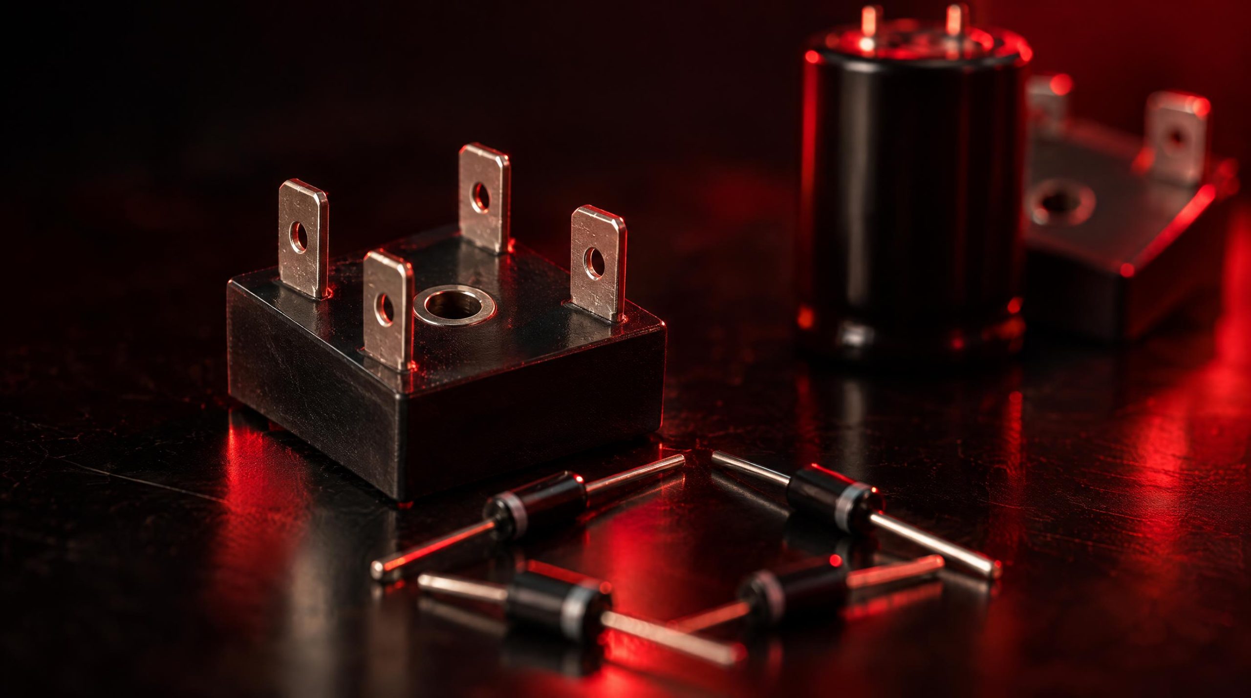
Rather than assembling four discrete diodes, many designs use pre-packaged bridge rectifier modules — single components containing all four diodes internally connected in the bridge configuration. These parts come in standardized through-hole packages (such as the KBP and KBPC series) as well as surface-mount versions, with current ratings from under 1 A up to several tens of amps and voltage ratings commonly from 50 V to 1000 V. The four connections — two AC inputs and positive and negative DC outputs — are clearly labeled, simplifying PCB layout and reducing assembly error. Heat dissipation is a factor for higher-current modules; ensuring adequate ventilation or a heatsink is important for reliable long-term operation.
Typical Applications
Both rectifier topologies appear across a wide range of systems. The full-bridge is by far the more common in modern designs, found at the front end of virtually every linear power supply and as the input rectifier stage of switch-mode power supplies — from laptop chargers and desktop computer power supplies to industrial motor drives and telecom power plants. Battery charging circuits, LED driver boards, UPS systems, and variable bench power supplies all rely on full-bridge rectification to convert grid AC into a controllable DC bus.
The center-tap configuration still appears in designs where a center-tapped transformer is already part of the architecture — certain audio amplifier power supplies, for instance, use a center-tapped secondary to produce both positive and negative supply rails simultaneously, with one diode pair rectifying each rail. It also turns up in low-voltage, high-current applications such as switch-mode secondary-side rectification in forward converters, where the lower diode drop of the two-diode center-tap circuit meaningfully improves efficiency compared to a full-bridge.
WIN SOURCE, a global independent distributor of electronic components, stocks rectifier diodes and bridge rectifier modules — along with Schottky and fast-recovery diodes, filter capacitors and the power management ICs that follow the rectifier stage — from manufacturers including Vishay, onsemi, Infineon, STMicroelectronics and Diodes Incorporated, covering current-production parts as well as part numbers that are hard to find, and supports shortage sourcing, lifecycle management and alternative solutions. Any substitute part is subject to final approval by the customer’s engineering team.
Conclusion
Half-bridge (center-tap) and full-bridge rectifiers both achieve full-wave rectification, and their core performance numbers — average output voltage at 0.637 × Vpeak, ripple factor of 0.48, and theoretical efficiency ceiling of 81.2% — are essentially identical. The practical differences come down to transformer complexity, diode count, voltage drop, and PIV requirements. The full-bridge needs no center-tapped transformer, places lower PIV demands on its four diodes, and uses the transformer more efficiently, making it the standard choice for the vast majority of single-phase power supply designs. The center-tap topology holds its ground where a single diode drop matters — low-voltage high-current applications — or where the transformer architecture makes it a natural fit.
Component selection follows from understanding these tradeoffs. Standard silicon rectifiers serve general-purpose mains-frequency work; Schottky diodes cut losses in low-voltage circuits; fast-recovery diodes are essential in switching converters. Integrated bridge modules simplify assembly and are available in a range of voltage and current ratings that cover most application requirements. Filtering with an appropriately sized electrolytic capacitor, followed by a linear or switching voltage regulator where tighter regulation is needed, completes the basic power supply chain built around either topology.
Frequently Asked Questions
What is the difference between a half-bridge and a full-bridge rectifier?
Both give full-wave rectification with the same 0.637 × Vpeak average output, 0.48 ripple factor and 81.2% theoretical efficiency. The half-bridge (center-tap) uses two diodes and a center-tapped transformer, loses one diode drop and needs diodes rated for twice the peak; the full-bridge uses four diodes on a plain secondary, loses two diode drops and needs diodes rated for only the peak, while using the transformer winding more fully.
How do I calculate the PIV rating for rectifier diodes?
In a full-bridge each diode blocks the secondary’s peak voltage: for 230 V RMS that is 230 × √2 ≈ 325 V, so 400 V-rated parts are the usual choice. In a center-tap rectifier each diode blocks the peak of the whole secondary — twice the peak of the half it conducts from — so for the same DC output it must withstand roughly 650 V and 800 V-rated parts are typical.
Why is the ripple frequency twice the supply frequency?
Because both halves of the AC cycle are rectified into positive pulses, the output pulses at 100 Hz on a 50 Hz supply or 120 Hz on 60 Hz. The filter capacitor recharges twice as often as in a half-wave circuit, so it needs only half the capacitance for the same ripple target.
When should I use Schottky diodes in a rectifier?
On low-voltage rails — 5 V and below — where the 0.7 V drop of standard silicon (1.4 V across a bridge) is a large fraction of the output. Schottky parts drop about 0.2–0.4 V but have higher reverse leakage and lower reverse-voltage ratings, so the PIV margin has to be rechecked.
Which diode should I use for a mains-frequency rectifier?
For general-purpose 50–60 Hz work at up to 1 A, the 1N4001–1N4007 family (50–1,000 V) is the standard pick, with the 1N4007 chosen when voltage headroom matters; the 1N5400 series covers 3 A. Above that, or to simplify layout, an integrated bridge module such as the KBP or KBPC series is common. Switch-mode stages above 10 kHz need fast- or ultra-fast-recovery diodes instead.
Part discontinued, obsolete or hard to find?
WIN SOURCE is a global independent distributor of electronic components, supporting component supply, shortage sourcing, lifecycle management and alternative solutions. Visual inspection, non-destructive testing and electrical testing are applied according to material risk, customer requirements and the applicable quality process, and orders are covered by the published return policy and a 3-year warranty on eligible components.
Stock and pricing are updated daily — search a part number or contact us for current availability, lead time and a quote.
© 2026 Win Source Electronics. All rights reserved. This content is protected by copyright and may not be reproduced, distributed, transmitted, cached, or otherwise used without the prior written permission of Win Source Electronics.
