
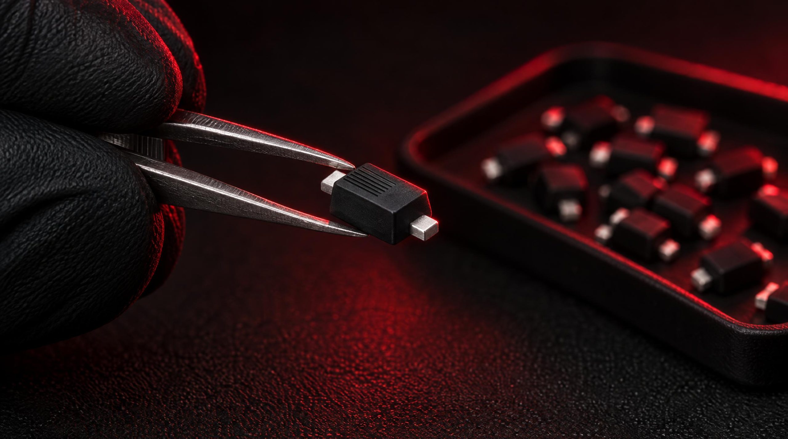
Rectifier diodes are among the most common discrete semiconductors in any electronics BOM. They appear in power supplies, motor drives, battery chargers, industrial controls, and countless legacy systems, often specified decades ago and still expected to perform reliably today. For most production designs, sourcing a 1N4007 or an SB340 is straightforward. The real engineering challenge lies in two less-discussed areas: selecting the right type of rectifier for a given application when multiple options exist, and locating the specific part number your circuit requires when that number has been discontinued, consolidated, or simply dried up in the market.
This article covers both. The first half explains the critical ratings on a rectifier diode datasheet, how those ratings interact with circuit topology, and how to compare standard, fast-recovery, Schottky, and silicon carbide diodes against real application requirements. The second half addresses the supply chain dimension: why rectifier part numbers go obsolete, what options exist when they do, and how to evaluate functional cross-references and alternative sourcing channels without compromising reliability.
What Rectifier Diodes Do
A rectifier diode is a PN junction semiconductor device designed to conduct current efficiently in one direction and block it in the other. In power electronics, this asymmetric behavior converts alternating current (AC) to pulsating direct current (DC), a process fundamental to nearly every power supply topology. The diode conducts when its anode is held at a higher potential than its cathode (forward bias), and it blocks when the polarity reverses (reverse bias). In a forward-biased silicon diode, the junction voltage drop typically falls in the range of 0.6 to 1.0 V depending on device design and forward current level; germanium devices drop somewhat lower, around 0.2 to 0.3 V.
Beyond simple AC-to-DC conversion, rectifier diodes appear as freewheeling diodes across inductive loads, as clamping diodes in snubber networks, as catch diodes in switching regulators, and as polarity protection elements at power supply inputs. Each use case places different stresses on the device, which is why understanding the individual ratings matters before settling on a part number.
Key Ratings Explained
Peak Inverse Voltage (PIV / VRRM)
Peak Inverse Voltage, also stated as the maximum repetitive reverse voltage (VRRM) on most modern datasheets, is the highest reverse-bias voltage the diode can withstand across its junction without entering avalanche breakdown. Exceeding this limit causes the PN junction to conduct in the reverse direction, typically resulting in thermal runaway and permanent damage. In practice, the PIV rating of a selected diode should carry a margin above the worst-case reverse voltage the circuit will ever apply, including transient spikes from inductive switching events and mains overvoltages.
A widely applied derating rule is to select a diode with a PIV rating at least 20 to 30 percent higher than the calculated peak reverse voltage in the application. For example, if analysis shows a maximum reverse voltage of 400 V, a diode rated at 500 V or higher provides a reasonable safety buffer. Rectifier diodes are available with VRRM ratings typically ranging from 50 V to well over 2,000 V, so there is rarely a reason to operate at the rated limit.
Average Forward Current (IF(AV))
The average forward current rating specifies how much rectified current the diode can sustain continuously without exceeding its maximum junction temperature under defined mounting conditions. This rating is measured under DC or half-wave conditions at a specified case or ambient temperature, so it is important to check the conditions on the datasheet and derate accordingly if your operating environment is warmer or your mounting is less thermally effective than the test setup. Selecting a diode whose IF(AV) comfortably exceeds the expected average load current, rather than operating near the rated limit, extends device lifetime and reduces the risk of thermal overstress.
Non-Repetitive Surge Current (IFSM)
At power-on, a filter capacitor on the output of a rectifier circuit can draw a very large inrush current for a brief period, often tens or hundreds of times the steady-state load current. The IFSM rating (also labeled IFPK or surge IF) specifies the maximum single-cycle surge current the diode can survive without damage. This parameter becomes critical when sizing rectifier diodes for mains-connected power supplies where a large bulk capacitor charges from near zero at turn-on. A common design approach is to verify that the expected inrush current, calculated from the capacitor value and the source impedance, stays below the IFSM figure with margin.
Forward Voltage Drop (VF)
The forward voltage drop is the voltage appearing across the diode when it conducts at the specified forward current. This parameter directly determines conduction losses: power dissipated in the diode equals VF multiplied by the average forward current. In low-voltage, high-current applications such as 5 V or 12 V switching regulators, even a 0.2 V difference in VF between two candidate diodes can meaningfully affect efficiency. Datasheets often include graphs of VF versus IF at multiple temperatures; consulting these curves rather than relying solely on the headline specification number gives a more accurate picture of real operating conditions.
Reverse Recovery Time (trr)
When a conducting diode transitions to reverse bias, stored minority carriers in the junction must be swept out before the device can block current. The time this takes is the reverse recovery time (trr). Standard general-purpose rectifiers have trr values in the range of several microseconds, which is acceptable for 50 Hz or 60 Hz power line rectification but causes significant switching losses at frequencies above a few kilohertz. Fast-recovery diodes reduce trr to several hundred nanoseconds, and ultrafast devices bring it below 100 ns. The shorter the recovery time, the lower the switching losses and EMI at a given frequency, making this specification critical for switch-mode power supply secondary rectifiers, freewheeling diodes, and any circuit operating above the audio-frequency range.
Junction Temperature and Thermal Resistance
All the current and voltage ratings on a diode datasheet are conditional on the junction temperature staying within the device’s maximum rating, usually 150 to 175 degrees Celsius for silicon. The thermal resistance from junction to case (RθJC) and from case to ambient (RθCA) allow engineers to calculate the expected junction temperature given the power dissipated and the thermal path to ambient. A device that meets all electrical specifications but overheats in its mounting configuration will fail prematurely. Thermal management, whether through heatsinking, forced airflow, or appropriate PCB copper pours, is therefore part of correct diode selection rather than an afterthought.
Rectifier Diode Types and When to Use Each
The term “rectifier diode” covers several distinct device families. They share the same basic function but differ substantially in switching speed, forward voltage, and voltage-handling capability. Choosing the wrong category is one of the most common design missteps, either leaving performance on the table or creating reliability problems.
Standard (General-Purpose) Rectifiers such as the 1N4001 through 1N4007 series and the 1N5400 through 1N5408 series are optimized for low-cost, low-frequency rectification at 50 or 60 Hz. Their trr values are measured in microseconds. They are the correct choice for transformer-based linear power supplies and other mains-frequency applications where switching speed is irrelevant. Using them in a switch-mode supply secondary is a design error: the slow recovery creates large reverse-current spikes, additional switching losses, and elevated EMI.
Fast-Recovery and Ultrafast Diodes are PN junction devices engineered for reduced minority carrier lifetime, bringing trr down to the 200 ns range for fast-recovery types and below 100 ns for ultrafast devices. They are well suited to higher-voltage rectification in SMPS topologies, inverter output stages, and motor drive freewheeling applications where the operating frequency exceeds a few kilohertz and the voltage exceeds the practical range of Schottky devices. Their forward voltage is generally comparable to standard silicon rectifiers.
Schottky Barrier Diodes replace the PN junction with a metal-semiconductor junction, which eliminates minority carrier storage entirely. The result is near-zero reverse recovery time and a significantly lower forward voltage drop, typically 0.2 to 0.45 V at moderate currents. These advantages make Schottky diodes the preferred choice for low-voltage, high-frequency secondary rectification in switching supplies, synchronous rectifier bypass diodes, and battery charging circuits. The trade-off is a practical upper voltage limit, usually around 200 V for silicon Schottky devices, combined with higher reverse leakage current and steeper leakage increase with temperature compared to PN junction types.
Silicon Carbide (SiC) Schottky Diodes extend the Schottky architecture to voltages of 600 V and above while retaining essentially zero reverse recovery. They have become standard components in high-efficiency power factor correction circuits and other demanding high-voltage, high-frequency applications where neither standard PN junction nor conventional silicon Schottky diodes are adequate. SiC devices carry a higher unit cost, but the system-level efficiency gains often justify the premium in high-power designs.
A concise rule of thumb: use standard rectifiers at mains frequency; use fast or ultrafast PN junction devices where voltage is high and frequency is moderate; use silicon Schottky devices where voltage is low and frequency is high; and use SiC Schottky devices where both voltage and frequency are high.
How Circuit Topology Affects Rating Requirements
The same AC source voltage places different voltage stresses on a rectifier diode depending on how the circuit is arranged. In a half-wave rectifier, each diode must withstand a peak inverse voltage equal to the peak of the AC input when a filter capacitor holds the output near the peak. For a 120 V RMS line, that peak is approximately 170 V, requiring a PIV rating well above that value to account for transients. A bridge rectifier connected to the same source spreads the voltage stress differently: each diode conducts through only half the bridge, and the PIV requirement is approximately equal to the peak AC voltage rather than twice that figure, as would be the case for a center-tap full-wave configuration.
In a center-tap full-wave rectifier, each diode sees a reverse voltage equal to the full secondary winding peak voltage, which is twice the peak voltage of one half-winding. This topology therefore requires diodes with roughly twice the PIV rating needed for the same output in a bridge configuration. Understanding this relationship prevents the common error of specifying diodes by output voltage alone without accounting for the topology’s stress multiplication. Where transients are poorly characterized, derating to 1.5 times the calculated peak reverse voltage, more conservative than the 20 to 30 percent baseline, is a sensible starting margin for general industrial designs.
A Practical Selection Checklist
With the individual ratings and device types in mind, the selection process for a rectifier diode follows a logical sequence. Working through these criteria in order prevents the most common oversights:
- Determine the maximum reverse voltage from the circuit topology and the worst-case input voltage, then add a 20 to 30 percent margin before setting the minimum VRRM.
- Calculate average and peak forward currents at full load and at power-on inrush, then confirm both fall within the device’s IF(AV) and IFSM ratings with thermal derating applied.
- Choose the diode family based on operating frequency: standard for 50/60 Hz, fast or ultrafast for intermediate frequencies in PN junction devices, Schottky for low-voltage high-frequency, SiC Schottky for high-voltage high-frequency.
- Check the forward voltage at the expected operating current and verify that the resulting conduction losses are acceptable for the efficiency budget.
- Verify package and thermal path: confirm that the chosen package can transfer enough heat at the expected power dissipation to keep junction temperature within rated limits.
- Confirm availability and lifecycle status of the exact part number before committing it to a BOM, particularly for designs expected to remain in production for several years.
That last point deserves more attention than it typically receives at the design stage, which leads directly into the sourcing side of this topic.
Obsolescence and the Supply Chain Problem
Rectifier diodes appear simple and commodity-like, and many of them are. The 1N4007 has been made by dozens of manufacturers for decades and faces no realistic shortage risk. But the category also contains tens of thousands of specific part numbers covering particular voltage grades, package styles, lead finishes, qualification levels, and performance grades that were specified for specific products and have not been updated since. When a manufacturer consolidates its portfolio, exits a market segment, or transitions to a newer process node, those part numbers disappear from active production with varying amounts of advance notice.
The scale of this problem is larger than many engineering teams realize. Not every end-of-life event arrives with a formal product discontinuance notice; the first signal engineers receive is often a stock depletion at distributors rather than an official warning. Industrial equipment, medical instruments, and defense and aerospace systems routinely have service lives of 10 to 30 years, far outlasting the 7 to 10 year typical lifecycle of a semiconductor product. A rectifier diode specified in a design from 2008 or 2012 may still be needed today for maintenance and repair of equipment still in active service, even though it has been out of production for years.
The costs of an unmanaged obsolescence event go beyond the component price itself. Emergency sourcing carries a premium. Unverified stock from unvetted suppliers introduces counterfeit risk. If no suitable stock exists, a redesign requires new layout work, testing, and in regulated industries, recertification, a process that can take months and carry very significant costs. Managing these risks proactively, rather than reactively, is what separates resilient supply chains from vulnerable ones.
Effective obsolescence management for rectifier diodes specifically should include monitoring lifecycle status at the BOM level, identifying single-source part numbers before they become a crisis, and maintaining relationships with sourcing partners who can locate legacy stock when needed. The same logic applies to shortage management during allocation events, when active parts temporarily become unavailable due to production shortfalls or demand spikes.
Strategies for Sourcing Obsolete or Hard-to-Find Part Numbers
When an exact rectifier part number is no longer available through standard distribution, the practical options fall into three broad categories: locating remaining new-old-stock (NOS) inventory, qualifying a functional equivalent from an active manufacturer, or redesigning the circuit if neither option is viable. In most cases the second option is preferable, but it requires careful technical validation.
Locating Remaining Stock. After a manufacturer discontinues a part number, inventory often persists across the distribution network for a period of time, sometimes years for high-volume commodity devices. Independent component distributors who specialize in extended market sourcing maintain access to these channels. When pursuing this route, the critical safeguards are working with distributors who carry recognized quality certifications, requesting full traceability documentation (date codes, country of origin, and manufacturer lot traceability), and testing samples upon receipt. Counterfeit rectifier diodes can pass visual inspection while failing under electrical stress, so what decides whether stock is safe to buy is how the supplier manages quality. The questions worth asking are the same whoever is quoting, and incoming inspection matched to the application’s risk is a necessary step rather than an optional one.
Qualifying a Functional Equivalent. Rectifier diodes from different manufacturers are often electrically interchangeable even when part numbers differ, because many devices in the category conform to JEDEC registered specifications or follow well-established industry-standard ratings. When evaluating a substitute, verify that the replacement meets or exceeds the original on all critical parameters: VRRM, IF(AV), IFSM, VF at operating current, trr if the circuit is frequency-sensitive, and junction temperature rating. Package compatibility is also required unless the board layout is being revised. Do not assume that devices with similar type numbers from different manufacturers are pin-for-pin and electrically identical without checking datasheets; suffix variations often indicate meaningful differences.
Redesign When Neither Option Is Viable. If the original part is truly unavailable and no direct equivalent exists, a circuit redesign may be required to accommodate a different voltage grade, package, or device family. In regulated industries this triggers a recertification process, so it is a significant undertaking. For non-regulated commercial products, a controlled design change with adequate testing is usually manageable. The cost of a redesign reinforces the value of proactive lifecycle monitoring: catching an obsolescence risk two years before production impact gives far more options than catching it after the last available stock is exhausted.
For teams managing large BOMs, BOM-level sourcing tools that cross-check part numbers against current availability and lifecycle status can identify at-risk components before they become production-stopping shortages. Combining this with a cost control strategy that includes strategic stocking of long-lead or near-EOL items reduces both risk and the price premium that comes with emergency procurement.
Cross-Referencing and Functional Equivalents
The rectifier diode market has a relatively well-established cross-reference tradition because so many part numbers in the category trace back to JEDEC registered devices or widely adopted industry standards. The 1N4001 through 1N4007 series, for example, are manufactured by a very large number of companies under the same designations, and a 1N4007 from one manufacturer is functionally interchangeable with a 1N4007 from another for virtually all applications. The 1N5400 through 1N5408 series follows the same pattern at 3 A. This standardization makes sourcing cross-references relatively straightforward for commodity devices.
Manufacturer-specific part numbers introduce more complexity. A company may have used a proprietary number for a device that is functionally equivalent to a standard JEDEC type, or for a device that was spec’d slightly differently from any standard type. In these cases, the cross-reference process involves extracting the key electrical parameters from the original datasheet (or from the markings on a failed component if the datasheet is no longer readily available), identifying active devices that meet or exceed those parameters, and confirming package compatibility. For automotive, medical, or aerospace applications, qualification level (AEC-Q101, for example) may also need to match. Independent distributors experienced in obsolete part sourcing can often assist with this matching process for specific part numbers, drawing on cross-reference databases and application knowledge built from handling similar situations across many customers. Final approval of any substitution belongs to the customer’s engineering team; a parametric match is necessary but not sufficient.
When the original part number falls in a less-standardized category, such as a high-voltage module rectifier, an automotive-grade device from a manufacturer that has since been acquired, or a device in a discontinued through-hole package, the cross-reference work requires more careful attention. Key parameters to verify include not just the headline voltage and current ratings but also the surge current capability, the recovery time class, the thermal resistance in the intended package, and the maximum operating temperature. A device that matches on three of five critical parameters and fails on the fifth will create a different failure mode from the original, which may not be obvious until field returns begin arriving.
WIN SOURCE, a global independent distributor of electronic components, supplies rectifier diodes covering current-production parts as well as parts that are hard to find or past end-of-life, and can support customers in identifying cost-effective alternative solutions when direct replacements are unavailable. It holds AS9120, ISO 9001:2015 and ISO 14001 certifications and is a member of ERAI, which supports the traceability and authenticity requirements of critical applications.
Conclusion
Selecting the right rectifier diode is not simply a matter of matching a voltage and current number to the headline ratings on a datasheet. Topology determines the actual PIV stress the device must withstand. Operating frequency determines which device family is appropriate. Thermal environment determines the effective current capacity in a given installation. Getting any one of these wrong produces a design that works in the lab and degrades or fails in the field.
The supply chain dimension adds a second layer of complexity that purely technical analysis cannot resolve. A well-selected rectifier diode that goes obsolete mid-production, or that turns out to be unavailable as genuine new stock, creates operational risk that can be as damaging as a design error. Treating lifecycle status and sourcing strategy as part of the component selection process, rather than as a procurement afterthought, is the more disciplined approach, especially for designs expected to remain in production or service for an extended period.
For engineers and procurement teams working with legacy designs, the combination of sound cross-reference methodology, verified sourcing channels, and proactive obsolescence monitoring provides the most reliable path to continuity. When genuine stock is available and alternatives exist, those options are far easier to evaluate before a shortage than during one.
Frequently Asked Questions
What is the difference between PIV and VRRM on a rectifier diode datasheet?
They describe the same limit. Peak Inverse Voltage (PIV) is the older term; most modern datasheets state it as the maximum repetitive reverse voltage (VRRM), the highest reverse-bias voltage the diode can withstand repeatedly without entering avalanche breakdown. Some datasheets also list a non-repetitive peak reverse voltage (VRSM) for single transient events, which is a separate, usually higher figure. Design to VRRM with a 20 to 30 percent margin above the worst-case reverse voltage your topology applies.
Can I replace a standard rectifier diode with a Schottky diode?
Only if the reverse voltage in the circuit stays within the Schottky device’s much lower voltage range, typically up to around 200 V for silicon Schottky parts. Within that range a Schottky diode offers lower forward voltage and near-zero reverse recovery, so it usually improves efficiency, but it also has higher reverse leakage that rises steeply with temperature. Check the leakage at your maximum operating temperature and confirm the package and pinout before substituting.
How much voltage margin should a rectifier diode have?
A common rule is to choose a VRRM at least 20 to 30 percent above the calculated worst-case peak reverse voltage, after accounting for the topology (a center-tap full-wave rectifier applies roughly twice the peak that a bridge does from the same secondary) and for line transients. Where transients are poorly characterized, a larger margin, such as 1.5 times the calculated peak, is a reasonable starting point for industrial designs.
Is a 1N4007 from one manufacturer interchangeable with one from another?
For virtually all applications, yes. The 1N4001 through 1N4007 series are JEDEC registered types, so any manufacturer using the designation is committing to the same headline ratings. Still read the two datasheets side by side before a substitution in a frequency-sensitive or thermally marginal circuit, because forward voltage curves, surge ratings and package variants can differ, and suffix letters often indicate meaningful differences.
What should I check before buying an obsolete rectifier diode part number?
Ask any supplier quoting the part for traceability documentation, including date codes, country of origin and manufacturer lot information, and for a Certificate of Conformance. Confirm what incoming inspection the supplier applies and how it is matched to the risk of the material, and check what the return policy and warranty cover. If a functional equivalent is offered instead, verify it against the original datasheet on VRRM, IF(AV), IFSM, VF, trr, junction temperature and package, and route the final substitution decision through your own engineering team.
Part discontinued, obsolete or hard to find?
WIN SOURCE is a global independent distributor of electronic components, supporting component supply, shortage sourcing, lifecycle management and alternative solutions. Visual inspection, non-destructive testing and electrical testing are applied according to material risk, customer requirements and the applicable quality process, and orders are covered by the published return policy and a 3-year warranty on eligible components.
Stock and pricing are updated daily — search a part number or contact us for current availability, lead time and a quote.
© 2026 Win Source Electronics. All rights reserved. This content is protected by copyright and may not be reproduced, distributed, transmitted, cached, or otherwise used without the prior written permission of Win Source Electronics.
