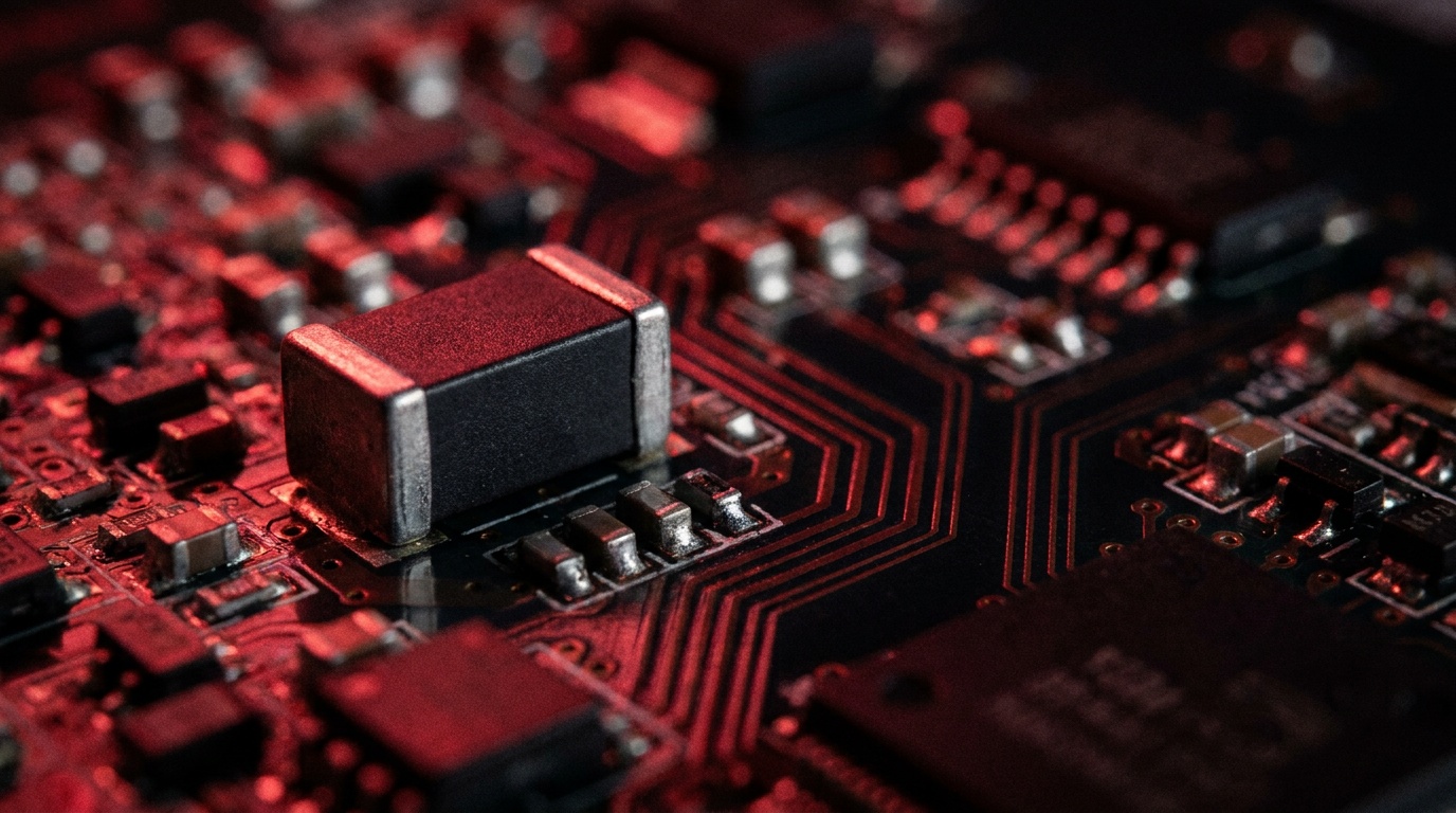
Every time a nearby lightning strike hits a power line, or a large motor switches off in an industrial facility, a voltage transient travels through the electrical system. These spikes can be brief — measured in microseconds — but the energy they carry is enough to destroy microcontrollers, power supplies, communication interfaces, and sensor circuits. The varistor, specifically the Metal Oxide Varistor (MOV), is the most widely deployed first line of defense against these events.
Despite being inexpensive and easy to integrate, varistors are frequently misapplied: wrong clamping voltage, undersized energy rating, or no coordination with upstream fusing. This reference guide covers how MOVs work at a physical level, what separates the different types of varistors, how to read and apply the key datasheet parameters for selection, and how to avoid the failure modes that cut protection short. It also compares MOVs with TVS diodes so you can choose the right technology for your application.
What Is a Varistor?
>What Is a Varistor?ial,Helvetica,sans-serif;font-size:12pt">A varistor — short for variable resistor, more precisely a voltage-dependent resistor (VDR) — is a passive two-terminal component whose resistance changes non-linearly with the voltage applied across it. Under normal operating conditions, its resistance is extremely high and it conducts almost no current. Once the voltage exceeds a defined threshold, resistance drops by several orders of magnitude, allowing the device to shunt large surge currents away from sensitive downstream components.The most common variant is the Metal Oxide Varistor (MOV), which dominates consumer electronics, industrial equipment, surge protection devices (SPDs), and power distribution systems worldwide. Its defining characteristic is bidirectional operation: it responds equally to positive and negative voltage transients, making it suitable for both AC and DC circuit protection.
How a Varistor Works
How a Varistor WorksHelvetica,sans-serif;font-size:12pt">The operating behavior of a varistor follows a highly non-linear current-voltage (I-V) relationship. The underlying physics involves the grain boundaries between zinc oxide ceramic particles inside the device. Each grain boundary behaves like a back-to-back pair of Schottky barriers — effectively a miniature zener diode junction. Because there are millions of these junctions distributed throughout the ceramic volume, energy from a surge is absorbed across the entire bulk of the material rather than concentrated at a single point, which gives MOVs their relatively high energy-handling capability compared to a single semiconductor junction.
During normal operation: The voltage across the varistor stays below its conduction threshold. All the grain-boundary junctions remain in a blocking state, resistance is in the megaohm range, and leakage current is negligible — typically in the microampere range. The varistor is electrically invisible to the circuit.
During a surge event: The voltage spikes above the varistor voltage (V1mA). The grain-boundary barriers break down in avalanche, resistance drops dramatically, and the device conducts hundreds or thousands of amperes for the duration of the transient — typically microseconds. Excess energy is dissipated as heat within the ceramic body. Once the surge passes, the barriers reform and the varistor returns to its high-resistance state automatically, with no external reset required.
This self-resetting behavior is one of the MOV’s practical advantages. It remains in-circuit and ready to protect against subsequent surges, unlike a fuse, which must be replaced after it operates.
Internal Structure of an MOV
>Internal Structure of an MOVica,sans-serif;font-size:12pt">An MOV is built from a sintered polycrystalline ceramic composed primarily of zinc oxide (ZnO) with small amounts of other metal oxides — commonly bismuth oxide (Bi2O3), antimony oxide, manganese oxide, and cobalt oxide. These additives control the grain size, grain-boundary chemistry, and the resulting electrical characteristics. The ceramic disk is compressed between two metallic electrodes, and the assembly is encapsulated in an epoxy or ceramic housing with wire leads (through-hole) or metal terminations (surface-mount).Physical size matters for performance. A larger disk diameter increases the cross-sectional area available for current conduction, raising surge current and energy ratings. Disk thickness determines the number of grain boundaries in series along the current path, which sets the varistor voltage. This is why high-voltage MOVs are physically thicker, and high-current MOVs are physically wider. Common disk sizes — designated by diameter in millimeters (7D, 10D, 14D, 20D) — map roughly to application tiers: small electronics, general power supply, industrial equipment, and high-surge environments, respectively.
Types of Varistors
Types of Varistorsans-serif;font-size:14pt;margin-top: 30px;margin-bottom: 15px">Metal Oxide Varistors (MOVs)
Metal Oxide Varistors (MOVs)ns-serif;font-size:12pt">MOVs are the dominant type in use today. Zinc oxide-based MOVs offer a superior non-linearity coefficient compared to older silicon carbide devices, a wide useful range of voltage and current ratings, fast response times in the nanosecond range, and a cost structure that makes them practical at volume. They are available in through-hole radial disk packages (the classic blue or green disk with two leads), surface-mount chip packages for board-level protection, and block or module configurations for panel-mount surge protection devices. Voltage ratings span from a few volts (for battery-powered and signal-line protection) up to hundreds of volts for AC mains applications.
Silicon Carbide Varistors (SiCVs)
<>Silicon Carbide Varistors (SiCVs)ns-serif;font-size:12pt">Silicon carbide varistors predate MOVs and were once the standard for high-voltage surge arresters. SiCVs have a less steep I-V curve (lower non-linearity coefficient), which means they conduct more current at normal operating voltages — generating continuous losses. For this reason, SiC surge arresters traditionally required a series spark gap to block leakage current during normal operation. Today, SiCVs have largely been displaced by MOVs in most new designs, but they retain a presence in legacy high-voltage power transmission applications where their ruggedness and established field history are valued.Package Variations
Package Variations-serif;font-size:12pt">Beyond the material distinction, varistors differ by package. Radial disk (through-hole) types are the most common for PCB assembly and provide the highest energy and surge current ratings for a given footprint. Surface-mount (SMD) chip varistors are used in compact consumer electronics and mobile devices where board space is limited, though they offer lower energy ratings. Multilayer chip varistors extend this further, offering very low clamping voltages suitable for protecting digital I/O lines. High-energy disk and block types are used in industrial panel boards, renewable energy inverters, and telecom equipment where large surge currents are expected.
Where Varistors Are Used
Where Varistors Are Used-serif;font-size:12pt">Varistors appear in almost every domain of electronic and electrical engineering. In consumer electronics and office equipment, MOVs are standard components inside power strips, AC adapters, and the power entry stage of computers, monitors, and smart home devices. Their job is to prevent grid transients — from switching events, capacitor bank operations, or indirect lightning — from reaching sensitive ICs and display drivers.
In telecommunications infrastructure, varistors protect the line-side circuitry of DSL modems, IP telephony equipment, and network switches from lightning-induced surges that travel along cable runs. These environments are particularly demanding because signal cables can carry surges over long distances with little attenuation.
In industrial automation, motor drive inverters, PLCs, and relay panels all generate switching transients through inductive load interruption. Varistors placed across contactor coils, motor terminals, and power supply inputs absorb these transients and prevent false triggering or component destruction in adjacent control circuits.
Renewable energy systems — solar PV inverters and wind turbine controllers in particular — face a combination of lightning exposure (due to outdoor siting), grid instability, and high-frequency switching. MOVs are installed at the DC input, AC output, and signal interfaces of inverters. They must handle both the high energy of lightning-coupled surges and the repeated low-energy transients from grid switching.
In automotive electronics, varistors (often multilayer chip types) protect ECUs, sensor lines, and communication buses (CAN, LIN, FlexRay) from load-dump transients, which can reach 60V or more on a 12V system when a running alternator is suddenly disconnected from the battery.
How to Select the Right Varistor: Key ParametersHow to Select the Right Varistor: Key Parameters
ont-size:12pt">MOV selection starts with five electrical parameters. Each one has a direct consequence for protection effectiveness and device longevity. Consulting the full datasheet — not just part number summaries — is essential before finalizing a choice.1. Maximum Continuous Operating Voltage (MCOV)
1. Maximum Continuous Operating Voltage (MCOV)size:12pt">MCOV is the highest RMS (AC) or DC voltage the varistor can sustain continuously without degrading. It is arguably the most critical selection parameter and also the most commonly misunderstood. Selecting an MCOV that is too close to the actual line voltage will expose the device to elevated leakage current during normal operation, gradually breaking down the zinc oxide grain boundaries even without a surge event. Good engineering practice calls for an MCOV at least 20–25% above the nominal system voltage. On a 120V AC line that points to an MCOV of 150V, the standard rating for that service; a 230V system takes 275V or above. Some designers apply a larger margin of 40% or more in environments with frequent voltage fluctuations or poor power quality.
2. Varistor Voltage (V1mA)
2. Varistor Voltage (V1mA)ze:12pt">The varistor voltage is the voltage across the device when 1 mA of DC test current flows through it. It marks the beginning of the conduction region and is the primary parameter used to match a varistor to a system voltage. For a 120V AC mains application, a V1mA of around 240V is typical. Setting this too low risks increased leakage during normal operation and accelerated aging. Setting it too high reduces the effectiveness of surge clamping, since the varistor won’t conduct until the voltage has already risen to a higher level.
3. Clamping Voltage (VC)
3. Clamping Voltage (VC)ze:12pt">Clamping voltage is the peak voltage measured across the varistor when a defined surge current (typically using an 8/20 μs waveform) flows through it. This is the voltage that downstream components actually see during a surge — so it must be lower than the withstand voltage (Vuw) of every component being protected. There is a trade-off: a lower clamping voltage provides tighter protection but means the varistor starts conducting sooner and absorbs more energy per event, accelerating wear. The practical goal is to select the lowest clamping voltage that remains comfortably above the system’s peak operating voltage, while staying below the protected equipment’s impulse withstand level.
4. Surge Current Rating (Ipeak)
4. Surge Current Rating (Ipeak)12pt">Surge current rating specifies the maximum peak current the varistor can handle without immediate failure, expressed for a standard 8/20 μs test waveform. The required rating depends on the exposure environment: indoor electronics are commonly specified in the low kiloamp range, industrial systems higher, and outdoor or telecom equipment higher still — the numbers your application needs come from its exposure category, not from a general table. It is worth noting that most manufacturers specify the surge current as a single-event rating — meaning the device should technically be inspected or replaced after absorbing a surge at this level. In practice, a varistor rated conservatively above the expected worst-case surge will have a longer service life, since each event consumes only a fraction of its total capability.
5. Energy Rating (WTM, in Joules)
5. Energy Rating (WTM, in Joules)>The joule rating describes the maximum single-pulse energy the varistor can absorb for a specified waveform. This must exceed the energy content of the largest surge the circuit is realistically expected to encounter. Underestimating this value can result in destruction of the MOV on the first major event. Physical size is the main determinant of energy capacity — a 20mm disk can absorb substantially more energy than a 7mm disk at the same voltage rating. When the expected surge energy is uncertain, erring on the side of a larger disk is almost always the right call, provided the board space and cost allow for it.
6. Capacitance
6. CapacitanceOVs add parasitic capacitance to the circuit, typically ranging from a few hundred picofarads for small chip types to several nanofarads for large disk types. In power supply protection, this is usually insignificant. However, in high-speed data lines, RF signal paths, or USB/HDMI interfaces, a standard MOV’s capacitance can distort signals or reduce bandwidth. For these applications, low-capacitance multilayer chip varistors or TVS diodes are typically preferred.
MOV vs. TVS Diode: Choosing the Right Technology
MOV vs. TVS Diode: Choosing the Right TechnologyOVs and Transient Voltage Suppressor (TVS) diodes are both widely used for surge protection, and they are often confused or treated as interchangeable. They are not. Each has distinct physical principles, trade-off profiles, and preferred application domains.
MOVs excel at absorbing high-energy transients. Their ceramic bulk construction allows them to handle thousands of joules and peak currents in the kiloampere range — making them the standard choice for AC mains protection, industrial panels, and outdoor equipment. Their granular structure, however, results in a relatively imprecise clamping voltage and adds significant parasitic capacitance. MOVs also degrade with each surge event: the grain boundaries experience cumulative stress, and over many events the MCOV drops until the device begins to conduct continuously, eventually leading to thermal runaway if not protected by a series fuse or thermal disconnect.
TVS diodes, by contrast, use semiconductor avalanche breakdown to clamp transients. They offer tighter, more precise clamping voltages, much faster response times (sub-nanosecond for unidirectional types), and are available in very low-capacitance configurations (below 1 pF) suitable for protecting high-speed digital interfaces like USB, Ethernet, and HDMI. Their weakness is energy handling: TVS diodes are rated in watts of peak pulse power rather than joules, and they cannot absorb the large energy levels that MOVs can. They are not suitable as standalone protection at the AC mains level.
In practice, these technologies are often combined in a coordinated protection scheme: a high-energy MOV at the power entry point clamps the bulk of a surge, followed by a TVS diode or low-capacitance chip varistor closer to the sensitive IC to tighten the clamp further. This staged approach, with adequate impedance (resistance or inductance) between each stage, distributes the surge energy and provides both high energy-handling capacity and precise voltage clamping where it matters most.
| Parameter | MOV | TVS Diode |
|---|---|---|
| Energy handling | High (joules to kJ) | Low to medium (watts) |
| Clamping precision | Moderate | High |
| Response time | Nanoseconds | Sub-nanosecond |
| Capacitance | High (100 pF – nF range) | Low options available (<1 pF) |
| Degradation | Cumulative with each surge | Minimal within rated limits |
| Best for | AC mains, industrial, outdoor | I/O lines, data interfaces, ICs |
Varistor Failure Modes and Safe Design Practices
Varistor Failure Modes and Safe Design Practicesstanding how MOVs fail is important for designing reliable protection circuits. There are three primary failure mechanisms, each with different causes and consequences.
Electrical Puncture
Electrical Puncturean MOV absorbs a surge that significantly exceeds its rated energy or current, a localized conduction filament can form within the ceramic body. This filament concentrates current in a narrow path, generating extreme local temperatures that can melt the bismuth oxide phase at grain boundaries. The result is a permanent low-resistance path — a pinhole puncture — through the device. At this point the MOV no longer functions as a protective element; it becomes a resistive short circuit.
Gradual Degradation
Gradual Degradationonly, MOV failure is gradual rather than catastrophic. Each surge event that the device handles degrades the grain-boundary junctions slightly, lowering the effective MCOV over time. As the MCOV decreases, the varistor begins to conduct more leakage current at normal operating voltage. This increased leakage causes additional heating, which accelerates further degradation — a positive feedback loop that can eventually lead to thermal runaway. The insidious aspect of gradual degradation is that it happens invisibly: the device may appear physically intact while having lost a significant fraction of its protective capability. Monitoring leakage current is the most reliable indicator of MOV health.
Thermal Cracking
Thermal Crackings are ceramic, they are susceptible to mechanical fracture when subjected to large, fast-rising surge currents. The rapid and non-uniform temperature distribution within the disk — caused by localized hot spots at grain boundaries — creates differential thermal expansion that can crack the ceramic body. A cracked MOV may still appear to function but will have compromised energy-handling capability and unpredictable clamping behavior.
Design Practice: Fuse and Thermal Coordination
Design Practice: Fuse and Thermal Coordinationd MOV (in short-circuit mode) can conduct continuous fault current from the mains, creating a fire risk, best practice requires placing a properly coordinated fuse in series with the varistor. The fuse must be fast enough to clear before the varistor reaches destructive temperatures, but not so sensitive that it opens during normal surge clamping events. Many commercial SPD modules also incorporate a thermal disconnect — a solder element that melts at a set temperature and physically disconnects the MOV from the circuit if it overheats. This provides a fail-safe even if the fuse does not respond quickly enough.
Advantages and Limitations
Advantages and Limitationsmargin-bottom: 15px">Advantages
- Advantagesh energy handling: MOVs can absorb far more energy than semiconductor-only solutions, making them effective against lightning-coupled transients and utility switching surges.
- Bidirectional operation: A single MOV protects against both positive and negative transients, simplifying AC circuit design.
- Self-resetting: The device automatically returns to its high-resistance state after a surge, requiring no manual intervention for continued protection.
- Cost efficiency: MOVs are among the lowest-cost passive protection components available at most voltage ratings and package sizes.
- No external control required: Varistors are autonomous — they need no bias, control signal, or active circuit to function.
Limitations
- Limitationsative degradation: Every surge event consumes part of the device’s lifetime. In high-transient environments, MOVs may need periodic replacement even if they have not failed visibly.
- Imprecise clamping: The grain structure of an MOV produces a relatively wide clamping voltage tolerance, which may be unacceptable for protecting low-voltage, high-sensitivity ICs.
- High parasitic capacitance: Standard disk MOVs are not suitable for protecting high-speed data or RF lines without capacitance mitigation.
- Fire risk on failure: An MOV that fails to a short circuit without a coordinating fuse or thermal disconnect can generate sustained heat and potentially cause a fire. This is not a hypothetical risk — it is a documented failure mode in surge protection devices built without that coordination.
- Not suitable for repetitive, high-energy environments without derating: In applications with frequent large surges (e.g., near heavy industrial switching), MOVs must be significantly derated or replaced more frequently to maintain reliable protection.
Frequently Asked Questions
Frequently Asked Questionsin-bottom: 15px">What is the difference between MCOV and varistor voltage (V1mA)?
What is the difference between MCOV and varistor voltage (V1mA)?ous Operating Voltage) is the highest steady-state voltage the device can sustain indefinitely without degradation. V1mA is a test parameter — the voltage at which 1 mA flows through the varistor under DC test conditions. V1mA is always higher than MCOV. When selecting a varistor for an AC application, MCOV is an RMS rating for AC use, and it should sit comfortably above the nominal line voltage — commonly 20–25% above — so that normal high-line conditions never push the device into conduction.
Can a varistor fail without any visible sign?
Can a varistor fail without any visible sign?he zinc oxide grain boundaries can reduce a varistor’s protective capability significantly before any physical damage is visible. A multimeter resistance check is a basic screening tool — a healthy varistor shows near-infinite resistance across its terminals under low test voltage. A more reliable method is to measure leakage current at rated MCOV: an elevated leakage current (compared to the original datasheet specification) is a reliable indicator of degradation.
Do varistors need to be fused?
Do varistors need to be fused?y environment where a failed varistor could draw continuous fault current, a series fuse or circuit breaker is strongly recommended. Without it, a varistor that fails to a short circuit will conduct line current indefinitely, potentially causing overheating and fire. Safety standards for surge protection equipment, such as IEC 61643-11 and UL 1449, address overcurrent coordination as part of SPD design; confirm what applies to your own product, market and certification program.
What happens if I choose a varistor with too low a clamping voltage?
What happens if I choose a varistor with too low a clamping voltage?age too close to the normal operating peak voltage will begin conducting during routine voltage variations on the line, not just during genuine surge events. This increases leakage current, generates heat, accelerates degradation, and can trigger nuisance tripping of upstream overcurrent devices. The correct approach is to select the lowest clamping voltage that still maintains a comfortable margin above the system’s maximum expected peak operating voltage.
How does disc size relate to varistor performance?
How does disc size relate to varistor performance? 14mm, 20mm) directly controls surge current capacity and energy rating. A larger diameter provides more cross-sectional area for current flow and more ceramic volume for energy absorption. Disc thickness controls the varistor voltage — thicker discs have more grain boundaries in series, resulting in a higher conduction threshold. When a design requires both high voltage rating and high surge current capacity, the result is a physically large component, which is why high-energy MOVs for industrial applications can be considerably bigger than the compact disk types used in consumer electronics.
Conclusion
Varistors — and M>Conclusiontors in particular — are practical, cost-effective, and well-understood components for transient overvoltage protection. When selected correctly, they are nearly invisible in a circuit during normal operation and respond autonomously to protect downstream components during surge events. When selected poorly — wrong MCOV, inadequate energy rating, or no fuse coordination — they can provide less protection than expected, degrade prematurely, or in the worst case create a fire hazard.
The key decisions in MOV selection are: set the MCOV with sufficient margin above the operating voltage, match the clamping voltage to what the protected components can tolerate, choose the energy and surge current rating for the actual exposure environment, and always coordinate with appropriate fusing or a thermal disconnect in AC mains applications. For high-speed signal lines or low-voltage IC protection, a TVS diode (alone or in combination with an upstream MOV) is often the better choice. Getting these decisions right at the design stage is far less costly than diagnosing field failures later.
Varistor discontinued, obsolete or hard to find?
Varistor discontinued, obsolete or hard to find?CE is a global independent distributor of electronic components, supporting component supply, shortage sourcing, lifecycle management and alternative solutions. Search a specific MOV part number against live stock, browse varistors and MOVs alongside the rest of the circuit protection range, or upload a full BOM to have alternates cross-referenced across every line. Where a direct replacement no longer exists, alternative solutions are worked up against your parameters — with final approval of any substitution belonging to your engineering team. Visual inspection, non-destructive testing and electrical testing are applied according to material risk, customer requirements and the applicable quality process, and orders are covered by the published return policy and a 3-year warranty on eligible components. Stock and pricing are updated daily — search a part number or contact us for current availability, lead time and a quote.
© 2026 Win Source Electronics. All rights reserved. This content is protected by copyright and may not be reproduced, distributed, transmitted, cached, or otherwise used without the prior written permission of Win Source Electronics.