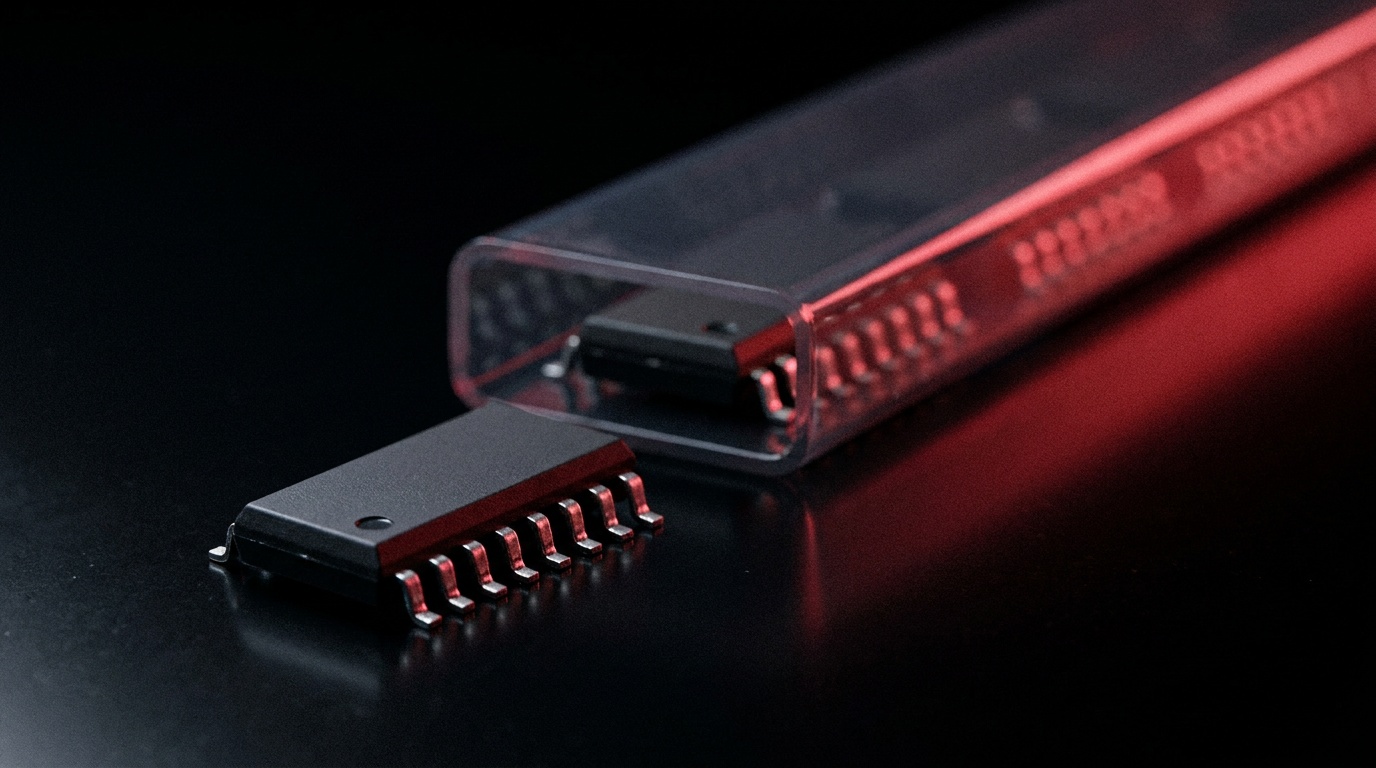
Every digital system — from a handheld calculator to an industrial controller running for two decades on a factory floor — is built on a small set of primitive switching elements called logic gates. They are the atoms of digital design: simple on their own, but capable of representing any computable function when combined. Of all the gate types, the inverter (or NOT gate) is the most fundamental, and understanding how it works is a natural starting point for understanding the rest.
This article is a reference guide. It covers what each gate type does, how logic families like TTL and CMOS differ in practice, and why sourcing obsolete or end-of-life (EOL) logic ICs has become a genuine supply chain challenge. Whether you’re a design engineer choosing between 74HC and 74LVC for a new board, a procurement specialist tracking down a discontinued part number, or simply someone who wants a clear explanation of the subject, the sections below should be useful.
What Is a Logic Gate?
What Is a Logic Gate?sans-serif;font-size:12pt">A logic gate is an electronic circuit that takes one or more binary input signals and produces a single binary output according to a fixed rule. Inputs and outputs exist in one of two states: logic 0 (LOW) and logic 1 (HIGH), typically represented by different voltage levels. In a standard TTL circuit, for example, a voltage below roughly 0.8 V is read as LOW and anything above about 2.0 V as HIGH. The specific thresholds vary by family, but the two-state principle is universal.
What makes gates useful is that their behavior is entirely deterministic. Given a specific combination of inputs, the output is always the same. That predictability is what allows billions of gates to be composed into processors, memories, and communication circuits that behave reliably at gigahertz speeds.
The Seven Basic Gate Types
The Seven Basic Gate Typessans-serif;font-size:12pt">There are seven standard gate types recognized in digital logic. Each is defined by its truth table — the complete mapping of every possible input combination to its corresponding output.
Inverter (NOT)
Inverter (NOT)ns-serif;font-size:12pt">The inverter has a single input and a single output. It simply reverses the logic state: a HIGH input produces a LOW output, and a LOW input produces a HIGH output. Its Boolean expression is written as Ȳ = Ā (the output equals the complement of the input). Despite its simplicity, it appears in virtually every digital design for signal complementing, feedback paths, and clock conditioning.
AND and NAND
AND and NAND-serif;font-size:12pt">An AND gate produces a HIGH output only when all of its inputs are simultaneously HIGH. Two inputs, for instance, yield a HIGH output only for the 1-1 input combination; all other combinations produce LOW. The NAND gate is the logical inverse: its output is LOW only when all inputs are HIGH and HIGH for every other combination. Because any logic function can be constructed from NAND gates alone, NAND is described as a universal gate.
OR and NOR
OR and NOR-serif;font-size:12pt">An OR gate produces a HIGH output whenever at least one input is HIGH. It only outputs LOW when all inputs are LOW. The NOR gate again inverts this: it produces a HIGH only when all inputs are LOW, making it LOW whenever any input goes HIGH. Like NAND, NOR is also a universal gate — any Boolean function can be built from NOR gates alone. The NAND and NOR pair are the most important gates in practical IC design for this reason.
XOR and XNOR
XOR and XNORerif;font-size:12pt">The XOR (exclusive-OR) gate outputs HIGH only when exactly one of its inputs is HIGH — that is, when the inputs differ. If both inputs are HIGH or both are LOW, the output is LOW. XOR gates are particularly useful in arithmetic circuits (binary adders rely on them) and in data comparison and error detection. The XNOR (exclusive-NOR) gate is the complement of XOR: it outputs HIGH when both inputs are in the same state, making it a natural equality comparator for two-bit values.
The Inverter Up Close: More Than a Simple Flip>The Inverter Up Close: More Than a Simple Flip
if;font-size:12pt">The inverter deserves a closer look because it appears in so many roles beyond straightforward signal complementing. At the transistor level, a basic inverter consists of a single switching device — an NPN bipolar transistor in older RTL and TTL designs, or a complementary PMOS/NMOS pair in CMOS implementations. When the input is LOW, the NMOS transistor is off and the PMOS is on, pulling the output HIGH. When the input goes HIGH, the situation reverses and the output is pulled LOW. This push-pull action is what gives CMOS its low static power dissipation: in either steady state, one transistor is fully off and there is very little current path from supply to ground.Beyond polarity inversion, inverters serve as signal buffers when chained in pairs (two inversions cancel out, restoring the original signal while re-driving it to full voltage and current levels). They also form the basis of oscillators, delay lines, and, when cross-coupled, the storage cells in SRAM. In short, the inverter is less a specialized gate than a fundamental building block that shows up across the entire landscape of digital design.
Schmitt-Trigger Variants: Cleaning Up Noisy Sign>Schmitt-Trigger Variants: Cleaning Up Noisy Signals
;font-size:12pt">A standard logic gate switches at a single threshold voltage. Any input that crosses that threshold causes the output to change state. In electrically noisy environments — near switching power supplies, motors, or long cable runs — a slowly-rising signal might bounce back and forth across the threshold multiple times, causing the output to toggle rapidly in an unintended way. This is where Schmitt-trigger inputs solve the problem.A Schmitt-trigger gate introduces hysteresis: two separate threshold voltages, one for the rising edge and one for the falling edge. Once the input rises above the upper threshold and switches the output, the input has to fall all the way below the lower threshold before the output will switch back. The gap between the two thresholds acts as a noise margin that rejects spurious transitions. Most logic families offer Schmitt-trigger versions of their standard gates — inverters, buffers, NAND, NOR, and XOR types are all available in Schmitt variants. They are the default choice for any input that may see slow edges, bouncing contacts, or conducted noise.
Logic Families: TTL, CMOS, and Everything in BetweenLogic Families: TTL, CMOS, and Everything in Between
size:12pt">A logic family is a group of integrated circuits that share common electrical characteristics — supply voltage range, input and output voltage thresholds, current drive, and switching speed — so that devices within the family can be directly interconnected without level-shifting circuitry. Choosing the wrong family, or failing to account for compatibility when mixing families, is a reliable source of hard-to-diagnose circuit failures.TTL and Its Sub-Families
TTL and Its Sub-Families:12pt">TTL (Transistor-Transistor Logic) uses bipolar junction transistors as its core switching elements and requires a 5 V supply. Texas Instruments introduced the original 7400-series in the mid-1960s, and it became a de facto standard that still defines part-numbering conventions today. The 7400 series eventually spawned numerous sub-families, each with a letter code inserted after the “74” prefix:
- 74 (standard TTL): The original family, now largely obsolete, with relatively high power consumption.
- 74LS (Low-power Schottky): Reduced power consumption with good speed; was for many years the most widely used sub-family for new designs.
- 74ALS (Advanced Low-power Schottky): Lower power and faster than 74LS, though stock is now limited and the family is not recommended for new designs.
- 74F (Fast): Higher speed variant intended for demanding timing-critical paths.
Military-spec variants use a 54-series prefix instead of 74, indicating a wider operating temperature range. The core logic function and pinout for any given number (e.g., 7404 or 5404, both hex inverters) are the same across military and commercial grades.
CMOS and Its Sub-Families
CMOS and Its Sub-Families:12pt">CMOS (Complementary Metal-Oxide-Semiconductor) technology uses paired PMOS and NMOS transistors. Its defining advantage over bipolar TTL is near-zero static power consumption: the circuit only draws significant current during switching transitions. This makes CMOS the dominant technology in virtually all modern digital ICs, from microcontrollers to memory to application processors. The 74-series numbering scheme was extended to CMOS, producing several important sub-families:
- 74HC (High-Speed CMOS): Matches 74LS speed with CMOS-level power; accepts a supply range of 2 V to 6 V. The recommended default for most new designs.
- 74HCT (High-Speed CMOS, TTL-compatible inputs): Same as 74HC but with input thresholds calibrated to accept TTL-level signals, making it a direct drop-in replacement for 74LS in mixed systems.
- 74AC / 74ACT (Advanced CMOS): Higher speed than 74HC, with stronger output drive. Useful in high-frequency or heavily loaded bus applications.
- 74LVC (Low-Voltage CMOS): Operates at 1.65 V to 3.6 V with 5 V-tolerant inputs on many devices, bridging 3.3 V and 5 V systems in modern mixed-voltage designs.
- 74AUP (Advanced Ultra-Low Power): Sub-1 V to 3.6 V supply, designed for battery-powered and energy-harvesting applications.
The older 4000-series CMOS family (CD4000 / HEF4000) operates over a wide voltage range of 3 V to 18 V and has been in production since the early 1970s. It is slower than 74HC but is still specified in many industrial and legacy designs for its wide supply tolerance and robustness in electrically harsh environments.
ECL: Speed at a Cost
ECL: Speed at a Cost:12pt">Emitter-Coupled Logic (ECL) operates differently from TTL and CMOS: it uses a differential transistor pair with current steering, and crucially, transistors never enter saturation. This eliminates the storage-charge delay that limits bipolar TTL speed, giving ECL propagation delays in the 1–2 ns range — the fastest of any standard logic family. The tradeoff is substantially higher power dissipation and poor noise immunity compared to CMOS. ECL appears in high-speed telecommunications, radar, and test equipment, but is rarely used in general digital design today.
Interfacing Between Families
Interfacing Between Familiest">Mixing logic families on the same board is common in practice but requires attention to voltage level compatibility. A standard TTL output driving a 5 V CMOS input is a classic problem: the TTL logic-HIGH minimum output of roughly 2.4 V falls below the CMOS logic-HIGH minimum input threshold of about 3.5 V, leaving a gap that can cause indeterminate switching. The solutions are straightforward: use 74HCT devices (which accept TTL-level inputs), add a pull-up resistor to raise the TTL output swing, or insert a dedicated level-shifting buffer. When moving from 5 V to 3.3 V systems (or lower), many 74LVC devices include 5 V-tolerant inputs that handle this transition without external components.
Universal Gates: Building Everything from NAND or NOR
Universal Gates: Building Everything from NAND or NORt">NAND and NOR gates are called universal gates because either one is sufficient to implement any Boolean logic function, including AND, OR, NOT, XOR, and any combination thereof. A NAND gate with all inputs tied together, for example, behaves as an inverter. An AND function is a NAND followed by an inverter (another NAND with tied inputs). An OR function requires three NANDs arranged appropriately.
This universality has practical implications. In a design that already uses NAND gates, spare gate sections can substitute for AND or OR or NOT functions without adding additional IC packages — a common glue-logic optimization. It also explains why manufacturers stock NAND and NOR devices in the broadest range of configurations: single-gate packages, quad 2-input, triple 3-input, dual 4-input, and 8-input versions all exist across major logic families from Texas Instruments, NXP, Nexperia, and others.
Sourcing Obsolete and End-of-Life Logic ICs
Sourcing Obsolete and End-of-Life Logic ICs>Logic gate ICs are among the longest-lived components in electronics. A design from the late 1980s or 1990s may still be in production — supporting legacy industrial equipment, medical devices, or aerospace systems — and require the exact same part numbers that were specified three or four decades ago. But component obsolescence is an ongoing reality. Manufacturers discontinue older process nodes to free capacity for advanced fabrication. A part that was easy to order last year may now quote a lead time that no longer fits your build schedule, or carry an end-of-life (EOL) notice. For long-life products, this creates serious supply continuity risk.
The problem is particularly acute for older logic families. Original 74-series TTL parts, 74ALS devices, and many 4000-series CMOS variants are at various stages of discontinuation. Even some 74HC and 74HCT types in specific package configurations — PDIP (plastic through-hole DIP), for instance — are seeing reduced availability as surface-mount packages take priority. When a critical part becomes unavailable, teams generally face a choice among four options:
- Last-Time Buy (LTB): Purchase enough inventory to cover all future production and service needs before the manufacturer closes the order book. Simple to execute but requires accurate long-range demand forecasting and working capital commitment.
- Alternative Sourcing: Locate stock held by independent distributors, excess inventory channels, or specialist obsolescence distributors. This is often the fastest path when LTB windows have already closed.
- Functional Equivalent or Drop-In Replacement: Identify a pin-compatible, electrically equivalent part from a different manufacturer or a different logic sub-family. For example, a 74LS04 hex inverter can in many cases be replaced by a 74HCT04, subject to verifying supply voltage, timing margins, and output drive requirements against the system design.
- Redesign: Replace the obsolete IC with a newer, actively supported device, which eliminates the long-term supply risk but requires engineering resources, board respins, and potentially regulatory re-qualification.
Choosing between these strategies depends on the product’s remaining service life, the cost of a redesign, and how quickly stock is needed. In many cases, the most economical near-term solution is to source remaining inventory through a specialist distributor while a longer-term redesign or alternative qualification proceeds in parallel.
When sourcing through independent channels, traceability and authentication matter. Counterfeit components are a documented risk in the open market, and logic ICs — including widely used 74-series parts — are not exempt. Working with distributors that hold recognized quality certifications such as AS9120 and ISO 9001, that are members of the industry reporting organization ERAI, and that can provide chain-of-custody documentation significantly reduces the risk of receiving remarked or non-conforming parts.
Proactive teams build resilience before shortages occur. This means maintaining a multi-source approved vendor list (AVL) for critical logic devices, monitoring manufacturer product change notices (PCNs) and EOL announcements, and considering form-fit-function alternatives during initial design rather than waiting for a procurement crisis. BOM analysis tools that flag lifecycle risk at the component level can surface potential problems years before they affect production schedules.
For teams managing logic IC supply across a product’s life, WIN SOURCE is a global independent distributor of electronic components, holding logic gates and inverters in current production alongside discontinued devices. Manufacturer names in this article identify the parts, nothing more. Where the original number is gone for good, alternative solutions are worked up against your parameters, and your engineering team signs off on whatever replaces the part.
Frequently Asked Questions
Frequently Asked Questions 30px;margin-bottom: 15px">Can I replace a 74LS part with the 74HC version of the same number?
Can I replace a 74LS part with the 74HC version of the same number?and the failure case is specific: 74HC input thresholds are set for CMOS levels, so a TTL output driving a 74HC input can land in the indeterminate band. 74HCT exists precisely for that situation, with TTL-compatible input thresholds and the same pinout. Check supply voltage, timing margin and output drive against the design before swapping either way.
Why are NAND and NOR called universal gates?
Why are NAND and NOR called universal gates?her one on its own can build every other function. A NAND with its inputs tied together is an inverter; a NAND followed by that inverter is an AND; three NANDs give an OR. The practical consequence is that spare sections in a NAND package can absorb stray glue logic instead of adding another IC.
When do I need a Schmitt-trigger input?
When do I need a Schmitt-trigger input?e input edge is slow or noisy — a signal off a long cable, an RC-delayed line, a mechanical contact, or anything running near a switching converter or motor. Hysteresis puts a gap between the rising and falling thresholds so the output cannot chatter as the input crawls through the switching region.
Which logic families are hardest to buy now?
Which logic families are hardest to buy now?oldest ones and the oldest packages: original 74-series TTL, 74ALS, and parts of the 4000-series, plus through-hole PDIP versions of families that remain available in surface-mount. Availability shifts constantly, so check the manufacturer’s lifecycle status for your specific part number rather than assuming a whole family is gone.
How do I reduce obsolescence risk on a new design?
How do I reduce obsolescence risk on a new design?ively supported family — 74HC, 74HCT or 74LVC for most work — approve more than one manufacturer for critical devices, subscribe to PCN and EOL notifications, and run BOM lifecycle checks periodically rather than at the point of a shortage. Footprint choices that accept more than one package widen your options later.
Conclusion
L>Conclusionne of the most thoroughly understood topics in electronics, but the practical details — how logic families differ in voltage levels and current drive, where Schmitt-trigger inputs are necessary, how to handle mixed-family interfaces — matter a great deal in real designs. The inverter, the most elementary gate, is in many ways the key to understanding the rest: its push-pull switching behavior, its role as a buffer and a building block for more complex functions, and its Schmitt-trigger variant all illustrate principles that apply across every gate type.
On the supply chain side, logic ICs sit at an interesting point: the technology is mature and well-understood, but many specific part numbers in legacy packages are slowly disappearing from active production. Engineering teams managing long-lifecycle products benefit from treating logic gate selection and obsolescence planning as early-stage design decisions rather than late-stage procurement emergencies. Knowing the functional equivalents between 74LS, 74HC, 74HCT, and 74LVC gives design engineers the flexibility to adapt when a specific part number is no longer available, and working with verified specialist distributors covers the cases where a direct replacement isn’t an option.
Logic IC discontinued, obsolete or hard to find?
Logic IC discontinued, obsolete or hard to find?ottom:16px">WIN SOURCE is a global independent distributor of electronic components, supporting component supply, shortage sourcing, lifecycle management and alternative solutions, and holding AS9120, ISO 9001:2015 and ISO 14001 certifications. Browse logic gates and inverters by family and package, search a specific 74- or 4000-series part number, or upload a full BOM to have lifecycle status and alternates checked across every line. Visual inspection, non-destructive testing and electrical testing are applied according to material risk, customer requirements and the applicable quality process, and orders are covered by the published return policy and a 3-year warranty on eligible components. Stock and pricing are updated daily — search a part number or contact us for current availability, lead time and a quote.
© 2026 Win Source Electronics. All rights reserved. This content is protected by copyright and may not be reproduced, distributed, transmitted, cached, or otherwise used without the prior written permission of Win Source Electronics.