
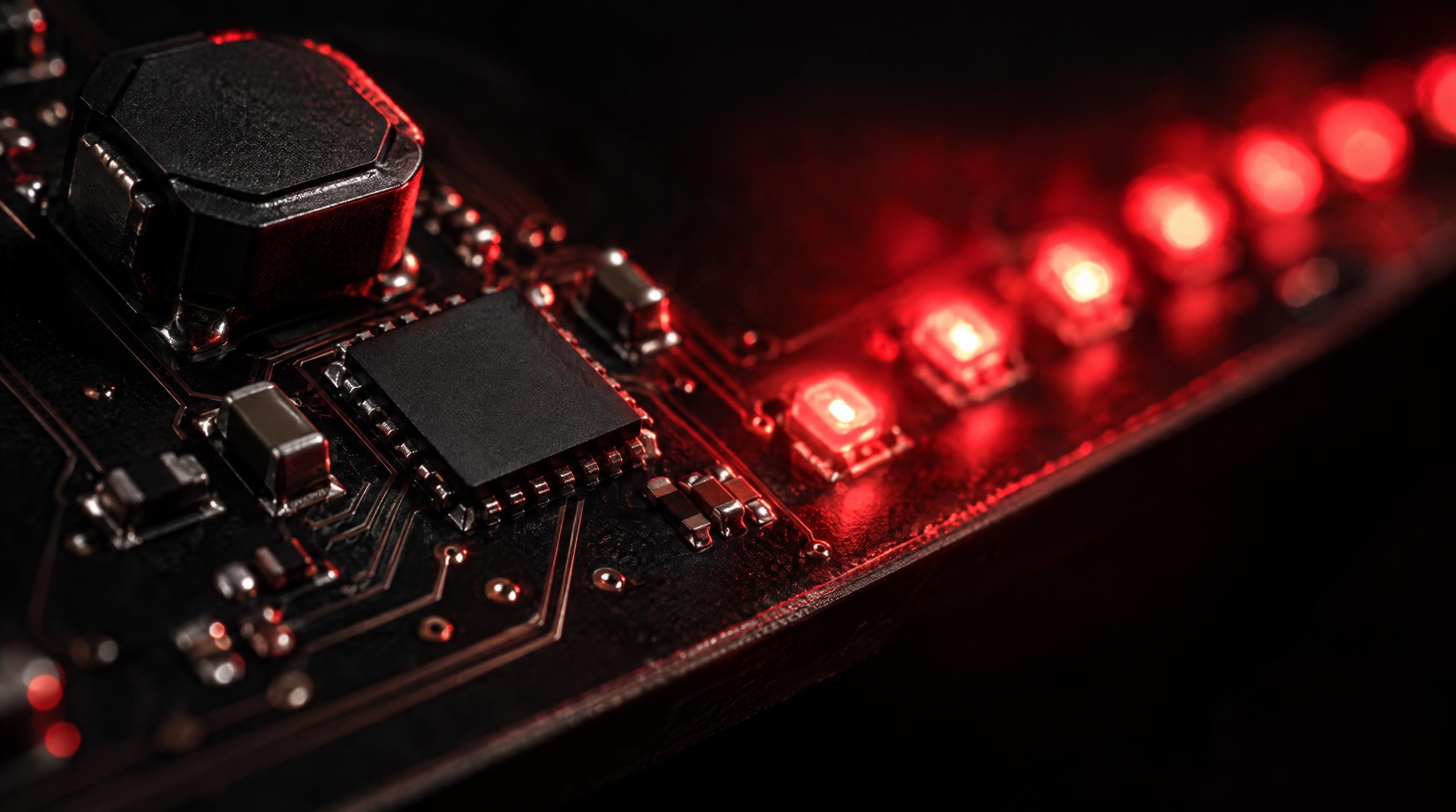
An LED driver IC is the component that sits between your power source and your LEDs, regulating current so that the light output stays stable, efficient, and within safe operating limits. Because LEDs are current-driven devices with a sharply nonlinear voltage-current relationship, even modest supply fluctuations can shift brightness noticeably or shorten LED lifespan — which is why the driver IC, not the LED itself, is often the most critical design decision in a lighting system.
This article covers the practical side of LED driver ICs: how the main converter topologies differ and when to use each one, how the major dimming methods compare, what specifications matter most during component selection, and how to handle the sourcing challenge that quietly affects many long-running designs — discontinued or end-of-life LED driver parts.
A complete technical breakdown of converter topologies, dimming methods, key specs, and strategies for sourcing discontinued LED driver components.
|
85–95%
Switching Efficiency
|
3000:1
PWM Dimming Ratio
|
|
5
Key Topologies
|
4
Dimming Methods
|
|
Linear vs. Switching Drivers
|
|
Linear Drivers
|
Switching Drivers
|
|
5 Key Switching Topologies
|
|
⬇️
Buck
Step-down. Use when Vin is always > LED string voltage. Ideal for 12 V / 24 V systems. |
⬆️
Boost
Step-up. Use when Vin is always < LED string voltage. Common in battery-powered devices. |
↕️
Buck-Boost
Up or down. Automotive-grade: handles 9 V–16 V+ input swing without losing regulation. |
|
Flyback
Isolated. Required for mains Class II luminaires, medical equipment, and offline LED supplies. |
SEPIC
Non-inverting buck-boost. Positive output rail, low ripple. Preferred for automotive LED apps. |
|
Dimming Method Comparison
|
|
PWM
On/off switching above flicker threshold. Color-stable across full range. Dimming Ratio 3000:1+
✅ Display, studio & architectural
|
ANALOG
Reduces drive current directly. Simple but causes color shift at low levels. Dimming Ratio 10:1–30:1
✅ Signage & basic indicator arrays
|
|
0–10 V
Legacy analog protocol. Simple wiring, wide hardware support. Susceptible to EMI on long runs. Addressing Group only
✅ Commercial lighting, retrofits
|
DALI
Digital 2-wire bus. Individual luminaire addressing, scene storage, status feedback. Addressing Individual
✅ Smart offices, BMS integration
|
|
Critical Specifications to Evaluate
|
|
Input Voltage Range
Must cover full supply swing incl. transients. Automotive needs >16 V headroom. |
Output Current Accuracy
Target ±1–5% channel-to-channel matching for uniform LED arrays. |
Switching Frequency
Higher freq = smaller passives, but more switching loss and EMI to manage. |
|
Thermal Shutdown
Check Tjmax and θja for real-world ambient temperature margins. |
Protection Features
OCP, OVP, open-LED, short-circuit. Verify fault behavior: latch-off vs. auto-restart. |
Package & Qualification
Automotive / industrial: AEC-Q100 required (–40°C to 125°C). Never substitute unqualified parts. |
|
Sourcing Discontinued & EOL Parts
|
⚠️ Key Risk: A driver IC designed in 5–10 years ago may now be end-of-life. Re-spinning around a new driver is expensive and time-consuming — plan ahead.
Purchase bridge stock during the 12–18 month EOL notice window. Risk: accurately forecasting multi-year demand tail. |
Pin-compatible alternative from another manufacturer. Verify electrical equivalence — protection thresholds and oscillator behavior can differ. |
Purchasable stock can still exist across a number of supply channels after last-time-ship. Ask whoever is quoting about inspection matched to the risk: electrical test, X-ray, marking verification. |
Ask whoever is quoting for AS9120 and ISO 9001 certifications, ERAI membership, and documented inspection and traceability procedures.
|
5 Key Takeaways
|
|
1
|
Topology first: Match converter topology to your Vin/Vout relationship and isolation requirements before evaluating any other parameter. |
|
2
|
Dimming method = system integration: PWM for color fidelity and high ratios; DALI for smart buildings; 0-10 V for simple retrofits. |
|
3
|
Automotive designs need AEC-Q100: Temperature grade and qualification status are non-negotiable — never substitute unqualified consumer parts. |
|
4
|
Plan for EOL before it hits: Monitor lifecycle notices, qualify alternatives, and build the supply relationship during product development — not after a shortage notice arrives. |
|
5
|
Counterfeit screening is mandatory: For scarce parts, ask whoever is quoting about AS9120/ISO 9001 certification, ERAI membership and verifiable inspection procedures. |
Global Independent Distributor of Electronic Components
WIN SOURCE is a global independent distributor of electronic components, supporting component supply, shortage sourcing, lifecycle management and alternative solutions — covering current-production LED driver ICs from TI, onsemi, Infineon, Analog Devices and others, as well as part numbers that are hard to find, with cross-reference support.
What Is an LED Driver IC?
What Is an LED Driver IC?At its core, an LED driver IC converts an input supply (AC mains, a DC bus, or a battery) into a regulated constant-current output matched to the forward voltage and current requirements of the LED load. The “constant current” requirement distinguishes LED drivers from standard voltage regulators. A series LED string shares the same current through every device, so the driver must maintain that current even as junction temperatures shift and forward voltages drift over time.
Driver ICs span an enormous range of complexity, from single-channel linear regulators used in indicator lights to multi-channel switching controllers managing kilowatt-scale arrays. Most modern drivers also incorporate protection features — overcurrent limiting, open-circuit detection, thermal shutdown — along with dimming interfaces. Understanding which architecture fits a given application is the first step in selecting the right part.
Linear Drivers vs. Switching Drivers
Linear Drivers vs. Switching Driversfundamental divide in LED driver design is between linear regulators and switching converters. Linear drivers regulate current by operating a pass element (typically a FET or bipolar transistor) in its linear region, dissipating excess input voltage as heat. The circuit is simple, requires few external components, and generates almost no electromagnetic interference — making it attractive for noise-sensitive environments such as medical imaging equipment or instrumentation backlight. The trade-off is efficiency: a linear driver powering a 3 V LED from a 12 V supply wastes roughly 75 percent of its input energy as heat, and that penalty scales with the voltage gap between input and the LED string voltage.
Switching drivers store energy in inductors or capacitors and release it to the load in controlled pulses, achieving efficiencies typically in the 85–95 percent range. That efficiency advantage makes switching architectures the default choice for anything above a few watts. The cost is greater design complexity, a larger external component count, and switching noise that must be managed through layout and filtering. For most lighting applications — general illumination, automotive headlamps, street lighting, display backlights — the efficiency gain justifies the added complexity.
One practical note: linear drivers are still the right answer for low-power applications where PCB space is tight, the input-to-output voltage differential is small, and EMI margin is limited. The decision is not always about raw efficiency; it’s about the full system context.
Switching Topologies: Buck, Boost, Buck-Boost, Flyback, and SEPIC
Switching Topologies: Buck, Boost, Buck-Boost, Flyback, and SEPICwitching driver family, topology selection hinges on the relationship between the input voltage and the required LED string voltage, as well as isolation requirements and EMI targets. The five topologies most commonly encountered in LED driver ICs are described below.
Buck (Step-Down)
Buck (Step-Down)verter is the workhorse of LED driver design when the input voltage is reliably higher than the LED string voltage. It steps input voltage down to match the LED load, maintains excellent current regulation, and achieves high efficiency with a relatively simple external circuit (one inductor, one capacitor, one diode or synchronous switch). Buck-topology drivers are common in 12 V and 24 V LED lighting systems, automotive interior lighting, and architectural LED fixtures where the supply rail is well-defined and always exceeds the string voltage. The limitation is that the converter cannot operate if the input voltage drops below the LED string voltage, which makes it unsuitable for applications with wide input ranges.
Boost (Step-Up)
Boost (Step-Up)put is always lower than the LED string voltage, a boost topology steps voltage up. This is common in battery-operated portable devices where a single-cell or two-cell lithium supply must drive a series string of white LEDs, and in mains-powered applications that use a low-voltage DC bus to supply a long series LED string. Boost converters are efficient and compact, but they require that the input voltage remain below the string voltage at all times. Efficiency degrades at high step-up ratios, and the output diode reverse recovery loss becomes significant at high switching frequencies.
Buck-Boost
Buck-Boostut voltage can be either higher or lower than the LED string voltage — as is common in automotive 12 V systems, where the battery voltage ranges from around 9 V during cold cranking to over 16 V during load dump — a buck-boost topology is needed. These converters can both step voltage up and step it down, giving them the flexibility to maintain constant LED current across a wide input range. Single-switch buck-boost designs tend to invert the output polarity (a consideration in circuit layout), while four-switch non-inverting buck-boost designs avoid that issue at the cost of higher component count. The boost-buck variant is particularly valued in automotive LED applications because it achieves low input and output ripple simultaneously — a property that simpler SEPIC designs do not share.
Flyback
The f>Flybackgy is derived from the boost converter but uses a coupled inductor (transformer) in place of a single inductor, which allows the output to be galvanically isolated from the input. Isolation is required in mains-connected class II luminaires, medical equipment, and any design where the LED load must be kept electrically separate from the primary-side circuitry. A single-stage flyback can also provide power factor correction, which simplifies the overall design for offline LED drivers. The topology’s limitations include sensitivity to transformer leakage inductance (which can cause voltage overshoot on the primary switch), a relatively high output current ripple at 120 Hz, and potential instability at deep dimming levels. Despite these trade-offs, the flyback remains one of the most widely used topologies in commercial and residential LED lighting power supplies because of its combination of isolation, reasonable efficiency, and low component count.
SEPIC
The SEP>SEPICEnded Primary Inductor Converter) is a non-inverting topology that, like the buck-boost, can operate with its input above or below the output voltage. Unlike the standard buck-boost, its output is positive-referenced, which simplifies feedback circuit design. SEPIC converters are a preferred topology in automotive LED driver applications because they handle the input and output voltage variations inherent in vehicle electrical systems without inverting the output rail. They use two inductors (or a coupled inductor) and a series capacitor, and they tend to have lower output current ripple than a single-switch buck-boost. The primary trade-offs are slightly higher component count and the need to manage the coupling capacitor between the two inductor windings.
Dimming Methods: PWM, Analog, 0-10V, and DALI
Dimming Methods: PWM, Analog, 0-10V, and DALIthe most application-sensitive aspects of LED driver selection. The four main methods each have distinct characteristics, and choosing the wrong one for a project creates problems that are difficult to fix after the system is installed.
PWM dimming works by switching the LED current on and off at a frequency above the threshold of human flicker perception, adjusting the duty cycle to control perceived brightness. The key advantage is that the LED always operates at its rated forward current when on, which means color point and color temperature remain consistent across the full dimming range. PWM dimming can achieve very high dimming ratios — 3000:1 and above — with good linearity, making it the standard choice for display backlights, studio lighting, and any application where color fidelity at low brightness levels matters.
Analog dimming adjusts the LED drive current directly, effectively reducing the forward current to lower brightness. It is simpler to implement — typically just a control voltage applied to a dedicated pin on the driver IC — but it introduces a color shift as the junction temperature changes with current level, and the dimming range is narrower than PWM (typically 10:1 to 30:1 for acceptable color stability). Analog dimming works well for applications where cost and simplicity take priority over precise color control, such as basic signage and indicator arrays.
0-10V dimming is a legacy analog protocol in which a control voltage between 0 V and 10 V sets the output level, with 10 V corresponding to full brightness and voltages near 0 V reducing output to a low but typically non-zero level. It is well-established in commercial lighting, simple to wire, and supported by a wide range of driver hardware. Its limitations are susceptibility to electromagnetic interference on long control runs and the inability to individually address luminaires within a circuit — changing the group requires rewiring.
DALI (Digital Addressable Lighting Interface) is a digital two-wire protocol that allows individual luminaires on a shared bus to be addressed, grouped, and controlled independently. It supports logarithmic dimming curves aligned with human visual perception, scene storage in ballast memory, and status feedback from the driver to the controller. DALI drivers carry a higher unit cost than 0-10V equivalents, and the control infrastructure is more involved to commission — but for commercial buildings, smart office environments, and any installation where zone flexibility or energy reporting matters, DALI provides a level of control that analog methods cannot match.
A practical note: some driver ICs support hybrid dimming, combining analog current reduction at the high end of the brightness range with PWM at low levels to extend the effective dimming range while minimizing flicker artifacts. This is especially useful in architectural and hospitality lighting where very low brightness levels are required without visible flicker.
Key Specifications to Evaluate
Key Specifications to Evaluateterface, several other specifications directly affect whether a driver IC will perform reliably in a given application. The following are the parameters worth reviewing carefully during component selection:
- Input voltage range: Confirm the driver can operate across the full supply range the system will see in practice, including transients. Automotive designs in particular require headroom for load-dump events above 16 V.
- Output current accuracy: Channel-to-channel and unit-to-unit current matching directly affects brightness uniformity across LED arrays. Look for accuracy specifications in the ±1–5% range for multi-channel drivers used in displays or architectural installations.
- Switching frequency: Higher switching frequencies allow smaller passive components (inductors and capacitors) but increase switching losses and EMI. Many drivers allow frequency adjustment or synchronization to avoid interference with sensitive circuitry.
- Thermal shutdown and derating: The driver’s maximum junction temperature and its thermal resistance (junction-to-ambient or junction-to-board) determine how much thermal margin remains at the maximum ambient temperature in the end application.
- Protection features: Overcurrent protection (OCP), overvoltage protection (OVP), open-LED detection, and short-circuit protection are standard in most modern drivers. The behavior at fault — whether the driver latches off, auto-restarts, or folds back current — varies by part and should match the application’s safety requirements.
- Package and qualification: Automotive and industrial designs require AEC-Q100 qualification (temperature grade typically –40°C to 125°C). Consumer parts without this qualification should not be substituted into automotive designs without re-evaluation.
It is also worth checking whether the driver IC is supplied from a single manufacturer or has approved second-source alternatives. Parts available from only one supplier carry inherent lifecycle risk, which connects directly to the sourcing challenge discussed in the next section.
Sourcing Discontinued and Hard-to-Find LED Driver ICs
Sourcing Discontinued and Hard-to-Find LED Driver ICshave finite production lives. Manufacturers periodically rationalize their product portfolios, and a driver IC that was designed into a product five or ten years ago may now be end-of-life (EOL) or actively discontinued. For products with long production runs — industrial lighting controllers, automotive platforms, medical equipment — this creates a real procurement problem: the design is locked, the qualification is complete, and re-spinning around a new driver IC is expensive and time-consuming.
Component obsolescence often leads to increased production costs, delays, and the need for expensive redesigns to accommodate alternative components. When a key driver IC is discontinued, procurement teams face three main options:
- Last-time buy (LTB): If the manufacturer announces EOL in advance (typically 12–18 months notice), purchasing a bridge stock sufficient to cover the remaining production horizon is the most straightforward approach. The risk is accurately forecasting demand over what may be a multi-year tail.
- Drop-in replacement: A functionally compatible part from another manufacturer that meets the same electrical specifications, fits the same footprint, and passes qualification testing. Finding verified cross-references requires careful datasheet comparison; pin-compatible does not always mean electrically equivalent, particularly for protection thresholds and oscillator behavior.
- Global sourcing: Once a part is past last-time-ship, purchasable stock can still exist across a number of supply channels, and locating it becomes a sourcing exercise rather than a catalog order. What decides whether that stock is safe to buy is how the supplier manages quality — inspection matched to the risk the material carries, which for a scarce driver IC may include electrical test, X-ray analysis and marking verification.
The counterfeit risk around scarce LED driver ICs is real. When a part becomes scarce, the incentive to introduce non-genuine material into the supply chain increases. The questions worth asking are the same whoever is quoting: which quality certifications it holds (AS9120 and ISO 9001 are the relevant ones), whether it is an ERAI member, and what its inspection, date-code and return policies say.
Proactive lifecycle management reduces the severity of these situations considerably. Monitoring manufacturer product lifecycle notices, maintaining an approved vendor list with at least one qualified alternative for high-risk driver ICs, and engaging supply chain partners before a shortage hits — rather than after — gives procurement teams room to act on favorable terms. Sourcing runs the length of a product’s life — prototype builds, volume production, and the years after a part is withdrawn while a fielded design still has to be supported — so the supply relationship that covers EOL parts, shortage sourcing and alternative solutions is worth building during development, not after the notice arrives.
WIN SOURCE, a global independent distributor of electronic components, stocks LED driver ICs across current-production and hard-to-find part numbers from manufacturers including Texas Instruments, onsemi, Infineon and Analog Devices, and supports shortage sourcing, lifecycle management and alternative solutions with cross-reference support — engaged as part of an ongoing supply strategy. Final approval of any substitute rests with the customer’s engineering team.
Final Thoughts
LED driver IC selection involves more d>Final Thoughtsht appear at first glance. The topology determines what input-output voltage relationships the driver can handle and sets the efficiency ceiling; the dimming method determines how well the system integrates with building controls and how the LEDs behave at the bottom of the brightness range; and the key electrical specifications set the boundaries of reliable operation under real-world conditions. Getting those decisions right at the design stage prevents costly field issues later.
The sourcing dimension is equally important and often underweighted early in a program. An LED driver IC that is readily available today may be on a lifecycle clock, and the designs that handle EOL disruptions best are the ones that identified the risk before it materialized. Whether that means qualifying an alternative, establishing a bridge-stock position, or building a supply relationship that covers the years after last-time-ship — the time to act is during the product development phase, not when the shortage notice arrives.
Frequently Asked Questions
Frequently Asked Questionsbetween a linear and a switching LED driver IC?
A linear driver regulates LED current by dropping the excess input voltage across a pass transistor as heat, so it is simple and nearly EMI-free but inefficient when the input is much higher than the LED string voltage. A switching driver stores energy in an inductor and delivers it in controlled pulses, reaching efficiencies typically in the 85–95% range at the cost of more external components and switching noise. Linear suits low-power, tight-space, small-voltage-gap designs; switching is the default above a few watts.
Which LED driver topology should I use?
It depends on the >Which LED driver topology should I use?en the input is always above the LED string voltage, boost when it is always below, buck-boost or SEPIC when it can be either (automotive 9–16 V rails), and flyback when galvanic isolation from the mains is required. Isolation, EMI targets and output ripple then narrow the choice.
PWM or analog dimming — which is better?
PWM keeps the LED a>PWM or analog dimming — which is better? so color stays consistent across very wide dimming ratios (3000:1 and beyond); it is the choice for displays and color-critical lighting. Analog dimming reduces the drive current, which is simpler but shifts color and limits the useful range to roughly 10:1–30:1. Some drivers combine both to extend the range without flicker.
What should I check before substituting a discontinued LED driver IC?
What should I check before substituting a discontinued LED driver IC?equency, protection thresholds and fault behavior (latch-off versus auto-restart), thermal ratings, package and pinout, and qualification grade (AEC-Q100 for automotive). Pin-compatible does not mean electrically equivalent, so a substitute needs bench validation, and final approval belongs to your engineering team.
What are the options when an LED driver IC goes end-of-life?
A las>What are the options when an LED driver IC goes end-of-life?drop-in alternative, or sourcing remaining stock once the part is past last-time-ship. Monitoring manufacturer lifecycle notices and keeping at least one qualified alternative on the approved vendor list for high-risk parts gives procurement time to choose rather than react.
Part discontinued, obsolete or hard to find?
WIN SOURCE is a globa>Part discontinued, obsolete or hard to find?, supporting component supply, shortage sourcing, lifecycle management and alternative solutions. Visual inspection, non-destructive testing and electrical testing are applied according to material risk, customer requirements and the applicable quality process, and orders are covered by the published return policy and a 3-year warranty on eligible components.
Stock and pricing are updated daily — search a part number or contact us for current availability, lead time and a quote.
© 2026 Win Source Electronics. All rights reserved. This content is protected by copyright and may not be reproduced, distributed, transmitted, cached, or otherwise used without the prior written permission of Win Source Electronics.
