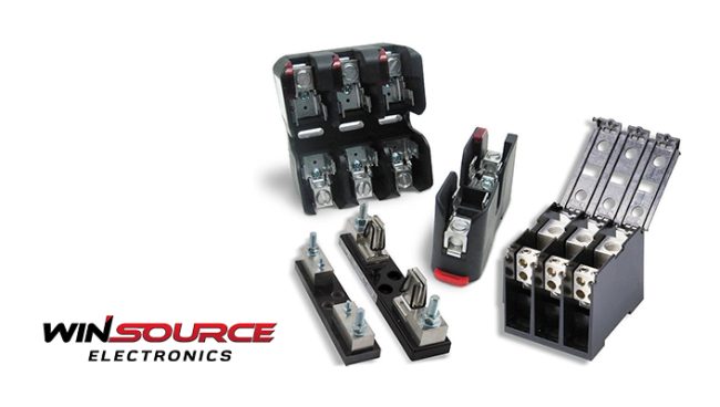
Fundamentals of a Fuse Holder
What is a fuse holder? In simple words, it’s a protective component designed to house and secure a fuse in an electrical circuit. Its primary function is to protect the circuit from overcurrent, preventing damage to sensitive components.
Types of Fuse Holders:
There are various types of fuse holders, with the plugin fuse holder being a common choice for PCB integration. The plugin fuse holder allows for easy replacement and maintenance, making it ideal for applications where accessibility is crucial.
Fuse Holder Design And Layout
1. Physical Layout:
When incorporating a fuse holder into a PCB design, the physical layout is of paramount importance. Careful consideration should be given to the placement of the fuse holder to ensure accessibility and ease of replacement. Engineers must factor in the overall dimensions of the fuse holder and allocate sufficient space on the PCB.
2. Current Ratings:
Understanding the current ratings of the fuse holder is critical for designing a reliable circuit. The current rating indicates the maximum current the fuse holder can handle without compromising its integrity. Engineers must choose a fuse holder with an appropriate current rating based on the specific requirements of the circuit.
3. Voltage Ratings:
Equally important is the voltage rating of the fuse holder. This parameter denotes the maximum voltage the fuse holder can withstand safely. Selecting a fuse holder with an adequate voltage rating is crucial to prevent electrical arcing and ensure the safety of the entire circuit.
4. Thermal Considerations:
Fuse holders can generate heat during normal operation. Engineers should consider the thermal properties of the fuse holder and its surroundings to prevent overheating. Proper heat dissipation mechanisms, such as thermal vias and strategically placed copper traces, should be incorporated into the PCB design.
Fuse Holder Integration Process
1. Footprint Design:
Creating an accurate footprint for the fuse holder is the first step in the integration process. The footprint should precisely match the dimensions of the chosen fuse holder, considering factors such as pin spacing and orientation. CAD tools can assist in generating precise footprints, ensuring compatibility between the PCB and the fuse holder.
2. Pad Placement:
Careful placement of pads for the fuse holder pins is crucial to establish a reliable electrical connection. One must adhere to the recommended pad layout provided by the fuse holder manufacturer. This ensures proper soldering and minimizes the risk of solder bridges or other soldering defects.
3. Signal Integrity:
Integrating a fuse holder into a PCB introduces a new component into the signal path. Signal traces should be routed with minimal impedance discontinuities, and additional measures, such as proper grounding techniques, should be employed to maintain signal integrity.
4. Mounting Mechanism:
Depending on the type of fuse holder, the mounting mechanism may vary. Make sure to carefully choose between through-hole mounting and surface-mount technology (SMT) based on the design requirements. Through-hole mounting provides mechanical robustness, while SMT offers space efficiency and streamlined assembly processes.
IV. Testing:
- Continuity Testing: Before finalizing the PCB design, continuity testing is essential to ensure that the fuse holder is electrically connected to the circuit. This step verifies the integrity of solder joints and the overall functionality of the fuse holder within the PCB.
- Current Overload Simulation: Simulating current overload conditions is a crucial aspect of testing fuse holder integration. Engineers can use specialized testing equipment to simulate overcurrent scenarios, validating the fuse holder’s ability to protect the circuit effectively.
- Environmental Testing: Fuse holders may be exposed to various environmental conditions during their lifecycle. Environmental testing, including temperature cycling and humidity testing, can uncover potential issues related to the long-term reliability of the fuse holder integration.
Practical Tips for Fuse Holder Integration:
1. Compatibility Check:
Ensure compatibility between the chosen fuse holder and the PCB design. Check for any mechanical or electrical mismatches that could compromise the performance of the fuse holder.
2. Documentation:
Comprehensive documentation is key to successful fuse holder integration. Maintain detailed records of the fuse holder specifications, PCB footprint, and any modifications made during the design process.
3. Standardization:
Standardizing the use of fuse holders across different PCB designs can simplify the design and manufacturing processes. This approach streamlines procurement and reduces the learning curve for assembly teams.
4. Accessibility:
Consider accessibility during the design phase. Optimal placement of the fuse holder on the PCB ensures easy replacement and maintenance, minimizing downtime during repairs.
Fuse holder integration in printed circuit boards demands a careful approach, taking into account various design considerations and adhering to industry best practices. With full comprehension of the fundamentals, carefully executing the integration process, and conducting thorough testing, engineers can ensure the reliability and safety of electronic circuits incorporating fuse holders.
Now, the question remains – where to get quality fuse holders from? Well, WIN SOURCE is a place where you can start. It’s a reputable electronic components distributor that offers premium quality products, including fuse holders as well.
© 2025 Win Source Electronics. All rights reserved. This content is protected by copyright and may not be reproduced, distributed, transmitted, cached or otherwise used, except with the prior written permission of Win Source Electronics.

COMMENTS