The Basics of Voltage Divider Circuits
As the name suggests, a voltage divider circuit divides an input voltage into two or more parts, with the output voltage being a fraction of the input voltage.
The most common voltage divider circuit consists of two resistors connected in series, and the output voltage can be found using Ohm’s Law.
Here’s a step-by-step explanation of how this formula works:
Step 1: Determine the Resistor Values
Before calculating the output voltage, you need to know the resistance values of R1 and R2. These values vary and are typically chosen based on the specific application and desired output voltage. Higher resistance values result in a smaller output voltage.
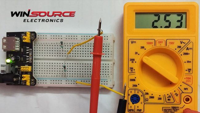
Step 2: Measure the Input Voltage
Measure the input voltage, Vin, which is the voltage across R1 and R2. You want to divide this voltage and obtain it as Vout.
Step 3: Apply the Voltage Divider Formula
Using the earlier formula, substitute the resistance values for R1 and R2 and the measured input voltage, Vin. The result will be the output voltage, Vout.
Advanced Voltage Divider Circuits
While the basic voltage divider circuit involves only two resistors, more complex applications may require additional components, such as potentiometers, transistors, or operational amplifiers (op-amps) , to achieve desired output voltages or to adjust the voltage division dynamically.
However, the core principle of voltage division remains the same, and it can be extended to circuits with multiple resistors in series or parallel.
Voltage Divider Rules
In essence, understanding voltage divider circuits involves grasping a few key principles and rules:
Series Resistance Adds Up
In a series circuit, like the one in a voltage divider, the total resistance is the sum of the individual resistances. For a basic voltage divider circuit, it’s RTotal = R1 + R2.
Voltage Drops Across Resistors
The voltage is divided across the resistors in a series circuit based on their resistance values. The voltage drop across each resistor can be calculated using Ohm’s Law, V = IR.
The Output Voltage is Proportional
The output voltage is directly proportional to the resistance of R2. As R2 increases relative to R1, Vout decreases, and vice versa. This is a crucial aspect of voltage dividers.
Keep Units Consistent
When working with the voltage divider formula, ensure that all resistance values are in the same unit (e.g., ohms) and that the input voltage is expressed in volts.
Special Cases
While the basic voltage divider formula works well for simple circuits, there are some special cases worth noting:
Equal Resistors
If R1 and R2 are equal, the output voltage will be half of the input voltage, effectively dividing it in half. This case is often used to create a midpoint reference voltage.
Voltage Dividers with More Resistors
In circuits with more than two resistors, the same principles apply. The voltage drop across each resistor can be found by dividing the resistance of that resistor by the total resistance.
Real-World Applications
Voltage divider circuits are not just theoretical concepts but have a multitude of practical applications in electronics and engineering:
Power Supplies
Voltage dividers are used in power supplies to create stable reference voltages for regulation and feedback control. They help maintain a consistent output voltage regardless of variations in input voltage.
Sensor Circuits
Sensors often provide variable voltage outputs based on a measured quantity (e.g., temperature, light intensity, or pressure). Voltage dividers are used to convert these variable voltages into a format that can be read by microcontrollers or other processing units.
Volume Control
In audio systems, potentiometers (variable resistors) are used in voltage divider configurations to control volume levels. By adjusting the potentiometer, the resistance ratio changes, thereby altering the output voltage and, consequently, the volume.
Biasing Transistors
Transistor biasing circuits, such as collector-base bias, use voltage dividers to set the operating point of the transistor. This ensures that the transistor operates in the desired region and amplifies signals accurately.
Level Shifting
Voltage dividers can be used to shift voltage levels. This is important when interfacing with different logic families or connecting components that require different voltage levels.
Limitations of Voltage Dividers
While voltage dividers are a useful tool in electronics, they have some limitations that should be considered:
Load Dependency
Voltage divider circuits are sensitive to the load connected to the output. If the load resistance is not high compared to R2, it can affect the accuracy of the output voltage.
Input Variations
Voltage dividers are not suitable for applications where the input voltage varies significantly. They do not provide regulation or stabilization of the output voltage, so any changes in the input voltage directly affect the output.
Current Draw
Voltage dividers draw a constant current from the source, which can be a disadvantage in low-power or battery-operated applications, as it leads to energy wastage.
In these kinds of cases, voltage regulators …or switching power supplies may be more suitable.
Understanding Voltage Divider Circuits – Rounding Up!
Voltage divider circuits are fundamental components in electronics, offering a simple yet effective way to obtain a desired output voltage from a supplied input voltage.
By understanding the principles of series resistance, voltage division, and Ohm’s Law, you can calculate the output voltage of a basic two-resistor voltage divider.
These circuits find applications in power supplies, sensors, audio systems, and transistor biasing, among others.
Overall, voltage dividers are an invaluable tool in electronics, and mastering their operation is essential for any aspiring electrical engineer or electronics enthusiast. Whether you’re building a simple circuit or working on a complex electronic project, the ability to calculate output voltages with voltage dividers is a skill that will serve you well.
For all your electronic component needs, contact WIN SOURCE today,
© 2025 Win Source Electronics. All rights reserved. This content is protected by copyright and may not be reproduced, distributed, transmitted, cached or otherwise used, except with the prior written permission of Win Source Electronics.
COMMENTS