* Question
What are the common port modes defined in the IEEE 1076 standard package?
* Answer
The IEEE 1076 standard—better known as the VHDL (VHSIC Hardware Description Language) standard—defines several port modes that specify the direction and behavior of signals interfacing with an entity.
These port modes determine how data flows between components in digital circuit descriptions, ensuring clarity, simulation accuracy, and synthesis consistency.
Below are the commonly used port modes defined in IEEE 1076.
1. in — Input Port
Definition
in ports accept data into an entity but do not allow assignment to the port inside the architecture.
Usage Scenario
Used when signals flow from external logic into the component.
Example:
Clock signals (clk), reset signals (rst_n), command codes, sensor input signals.
2. out — Output Port
Definition
out ports allow the entity to drive data outward, but traditionally restrict internal reading of the port value.
Usage Scenario
Used when the component generates output values for other modules.
Note:
Some synthesis tools allow reading an out port internally, but this behavior is not universally guaranteed by the original standard.
3. inout — Bidirectional Port
Definition
inout ports support both input and output operations.
Only one driver should be active at a time to avoid signal contention.
Usage Scenario
Used for tri-state buses, shared data lines, and external memory interfaces.
Examples include address/data buses connected to components such as SRAM, Flash memories, or microcontrollers (e.g., bidirectional pins on the 8051 MCU).
4. buffer — Output with Internal Feedback
Definition
buffer is similar to out, but the signal can be read internally within the entity.
Usage Scenario
Used when a module outputs a signal but also needs to monitor or reuse the same signal internally.
Note:
Modern VHDL practice strongly discourages buffer because it complicates synthesis; many engineers replace it with out plus an internal signal that mirrors the output.
Extended Note: IEEE 1076-2008 Enhancements
The 2008 revision introduced clarifications and improved modeling practices, but the four fundamental port modes remain unchanged:
- in
- out
- inout
- buffer
In addition, VHDL modeling techniques increasingly favor resolved signal types and internal signal duplication over the heavy use of buffer.
Engineering Insight
Choosing the correct port mode impacts:
- Synthesis results
- Simulation accuracy
- Hardware compatibility
- Tri-state bus behavior
- Readability of system architecture
For example, FPGA devices like those from Xilinx (AMD) or Intel (Altera) often map inout ports to physical tri-state pins, while buffer may not be supported in some synthesis tools.
Understanding port modes is fundamental when designing digital logic interfaces, SoC modules, or RTL components in a structured and maintainable VHDL codebase.
Conclusion
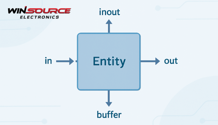
The IEEE 1076 (VHDL) standard defines four common port modes:
- in— input-only
- out— output-only
- inout— bidirectional
- buffer— output with internal readability
These modes describe how data flows between VHDL entities and external hardware, and they remain essential to modern digital design practices.
COMMENTS