* Question
What is included in the CPU Interrupt Enable Register?
* Answer
The CPU Interrupt Enable Register (often abbreviated as IE or INT_EN) is a special control register within a CPU or microcontroller that determines which interrupts are allowed to trigger the processor’s interrupt handling mechanism. Here’s a detailed breakdown of what it typically includes:
Table of Contents
ToggleOverview: What Is the CPU Interrupt Enable Register?
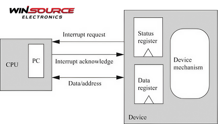
The Interrupt Enable Register is used to mask (disable) or unmask (enable) specific interrupt sources. By setting or clearing bits in this register, software can control which peripheral or system events are allowed to interrupt the CPU.
It plays a central role in interrupt-driven systems, where events like timer overflows, external signals, or UART data reception need to be handled immediately by interrupt service routines (ISRs).
Typical Contents of an Interrupt Enable Register
The exact layout depends on the CPU architecture (e.g., ARM Cortex-M, x86, AVR, MIPS, RISC-V), but generally includes bit fields for each interrupt source:
Bit Position | Name | Description |
Bit 0 | INT0_EN or TIMER0_IE | Enables interrupt from external pin 0 or Timer 0 overflow |
Bit 1 | INT1_EN or TIMER1_IE | Enables interrupt from external pin 1 or Timer 1 |
Bit 2 | UART_RX_IE | Enables UART receive interrupt |
Bit 3 | UART_TX_IE | Enables UART transmit complete interrupt |
Bit 4 | ADC_IE | Enables ADC (Analog-to-Digital Converter) conversion complete interrupt |
Bit 5 | GPIO_IE | Enables GPIO port change or pin interrupt |
Bit 6 | I2C_IE | Enables I2C-related interrupts (e.g., bus activity or data received) |
Bit 7 | SPI_IE | Enables SPI transmission/reception complete interrupt |
These bits are writeable, and:
Setting a bit to 1 enables that interrupt source.
Setting a bit to 0 disables it.
Global Interrupt Enable
Some CPUs (especially microcontrollers) include a global interrupt enable bit, often outside this register:
In AVR: Bit I in the SREG (Status Register)
In ARM Cortex-M: PRIMASK register controls global interrupt masking
In x86: IF (Interrupt Flag) in the EFLAGS register
This global bit must also be set to allow any interrupt to be acknowledged by the CPU.
Example: 8051 Interrupt Enable Register (IE)
For the Intel 8051 microcontroller family, the IE register layout is as follows:
| EA | — | ET2 | ES | ET1 | EX1 | ET0 | EX0 |
EA: Global enable/disable for all interrupts
ET0, ET1, ET2: Timer 0, 1, 2 interrupt enables
EX0, EX1: External interrupts 0 and 1
ES: Serial port interrupt enable
Usage in Code
In embedded C:
IE |= 0x01; // Enable external interrupt 0
IE &= ~0x08; // Disable serial port interrupt
In ARM CMSIS:
NVIC_EnableIRQ(UART0_IRQn); // Enable UART0 interrupt
NVIC_DisableIRQ(TIMER1_IRQn); // Disable Timer1 interrupt
Summary
The CPU Interrupt Enable Register includes:
Individual bits for enabling/disabling specific interrupt sources
Often tied to peripherals like timers, UART, ADC, GPIO, etc.
Works alongside a global interrupt enable flag
Allows fine-grained control over what events are allowed to interrupt the CPU
It is a critical component in designing responsive embedded systems and is typically configured during system initialization or as part of dynamic interrupt control.
COMMENTS