Three-axis magnetometers are used for heading, map rotation, robotic navigation, asset tracking, and magnetic-field event detection. Selecting the right device requires considering not only range, noise, and current, but also interface type, digital thresholds, package pinout, and whether an accelerometer is required for tilt compensation.
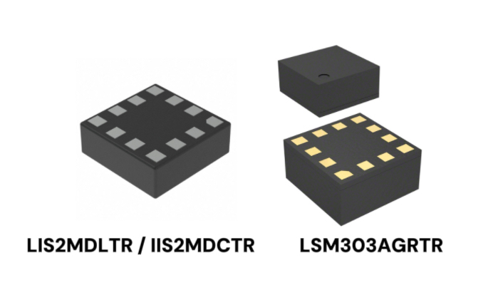
The STMicroelectronics LIS2MDLTR is a general-purpose standalone magnetometer. The IIS2MDCTR offers a similar magnetometer architecture in the same package for industrial designs that require long-term product availability. The LSM303AGRTR integrates a three-axis accelerometer with a similar magnetometer block.
Parameter Comparison
| Parameter | LIS2MDLTR | IIS2MDCTR | LSM303AGRTR |
| Sensor composition | 3-axis magnetometer | 3-axis magnetometer | 3-axis magnetometer + 3-axis accelerometer |
| Magnetic range and output | ±49.152 G typ.; 16 bit | ±25 G min., ±49.152 G typ.; 16 bit | Mag.: ±49.152 G typ., 16 bit; accel.: ±2/±4/±8/±16 g |
| Sensitivity and noise | 1.5 mG/LSB, ±7%; 3 mG RMS | 1.5 mG/LSB, ±7%; 3 mG typ., 4.6 mG max. | Mag.: 1.5 mG/LSB, ±7%; 3 mG RMS |
| Output data rate | Continuous: 10/20/50/100 Hz; single: up to 150 Hz | Continuous: 10/20/50/100 Hz; single: up to 150 Hz | Mag.: same; accel.: commonly 1–400 Hz |
| Typical operating current | 20 Hz: HR 200 µA, LP 50 µA; power-down 1.5 µA | 20 Hz: HR 200 µA, LP 50 µA; power-down 1.5 µA | Mag.: same; accel. at 50 Hz: about 7.7–12.6 µA; power-down 2 µA |
| Interfaces | I²C to 3.4 MHz; 3-/4-wire SPI to 10 MHz | I²C to 3.4 MHz; 3-wire SPI only, to 10 MHz | I²C to 3.4 MHz; mag. uses 3-wire SPI; two CS pins |
| Supply and logic levels | Vdd/Vdd_IO 1.71–3.6 V; VIH≥0.7, VIL≤0.3 × Vdd_IO | Vdd/Vdd_IO 1.71–3.6 V; VIH≥0.8, VIL≤0.2 × Vdd_IO | Vdd 1.71–3.6 V; Vdd_IO 1.71 V to Vdd+0.1 V |
| Package and replacement | 2.0 × 2.0 × 0.7 mm; LGA-12L | 2.0 × 2.0 × 0.7 mm; high reuse with LIS2MDL for I²C/3-wire SPI | 2.0 × 2.0 × 1.0 mm; different pins; not drop-in |
Application Fit
- LIS2MDLTR
Best for: Products that require standalone three-axis magnetic sensing and prioritize compact size, low current, an optional four-wire SPI interface, or reuse of an existing LIS2MDL design. Typical applications include handheld compasses, map rotation, consumer electronics, game controllers, and battery-powered positioning nodes.
Key takeaway: The LIS2MDLTR provides a typical ±49.152-gauss dynamic range, 1.5 mGauss/LSB sensitivity, and up to 100 Hz in continuous mode. Typical current at 20 Hz is 200 µA in high-resolution mode or 50 µA in low-power mode. It is the only device in this comparison whose magnetometer supports both three- and four-wire SPI.
- IIS2MDCTR
Best for: Standalone magnetic sensing in industrial equipment, robotics, instrumentation, and products that place greater emphasis on an industrial product line and long lifecycle while retaining performance close to the LIS2MDL.
Key takeaway: The IIS2MDCTR closely matches the LIS2MDLTR in core magnetic specifications, register map, and 2.0 × 2.0 × 0.7 mm package. Its datasheet lists 3 mGauss RMS typical and 4.6 mGauss maximum characterized noise, but its SPI interface is three-wire only and its digital input thresholds are stricter.
- LSM303AGRTR
Best for: Tilt-compensated e-compasses, orientation, free-fall, and motion detection where magnetic and acceleration data should come from one compact device. Typical applications include navigation terminals, wearables, and small mobile robots.
Key takeaway: The LSM303AGRTR magnetometer has range, sensitivity, ODR, and current consumption similar to that of the LIS2MDLTR while adding a ±2/±4/±8/±16 g accelerometer. The tradeoffs are a 1.0 mm package height, different pin functions, and approximately 7.7–12.6 µA of additional accelerometer current at 50 Hz.
Design Considerations
- Confirm Whether Tilt Compensation and Motion Detection Are Required
Choose the LIS2MDLTR or IIS2MDCTR when only magnetic-field measurement or magnetic-threshold events are required. A compass used at varying tilt angles requires tilt compensation, typically using the gravity vector measured by an accelerometer; the integrated accelerometer in the LSM303AGRTR supports this function and reduces the external component count.
Do not choose the integrated device solely because it is newer or more integrated. If acceleration data is already available from an IMU, a standalone magnetometer may be simpler and more efficient.
- Compare Noise and Current Under the Same Operating Conditions
At 20 Hz with offset cancellation disabled, all three magnetometer blocks typically draw about 200 µA in high-resolution mode or 50 µA in low-power mode. Enabling offset cancellation raises these values to approximately 235 µA and 100 µA at the same ODR.
The 3 mGauss RMS noise figure also assumes high-resolution operation with the low-pass filter or offset cancellation enabled. It should not be quoted without the operating condition.
- Check SPI Mode Before Treating Parts as Replacements
Pin 7 of the LIS2MDLTR can operate as the SDO pin for four-wire SPI or as INT/DRDY. The IIS2MDCTR and the LSM303AGRTR magnetometer support three-wire SPI only. A four-wire LIS2MDL design therefore cannot accept the IIS2MDC as a direct replacement.
I²C and three-wire SPI designs offer greater reuse between the two standalone parts, subject to a final review of pin usage and electrical thresholds.
- Verify Supply Rails, Digital Thresholds, and Combined Current
The LIS2MDLTR and IIS2MDCTR support Vdd and Vdd_IO from 1.71 to 3.6 V. The IIS2MDC requires VIH ≥ 0.8 × Vdd_IO and VIL ≤ 0.2 × Vdd_IO, compared with 0.7 and 0.3 ratios for the LIS2MDL.
For the LSM303AGRTR, Vdd_IO must not exceed Vdd + 0.1 V. When the accelerometer is enabled, its current must be added to the magnetometer current when estimating the total sensor budget.
- Review PCB, Driver, Magnetic Interference, and Calibration During Migration
The LIS2MDLTR and IIS2MDCTR share WHO_AM_I = 0x40 and closely aligned magnetometer registers, but pin 7 and the digital input levels still require review. The LSM303AGRTR is not a drop-in replacement despite its 2 × 2 mm LGA-12 footprint because pins 2, 11, and 12 have different functions.
Keep high-current traces away from the sensor, and validate hard-iron, soft-iron, assembly, and enclosure effects in the finished product. Production calibration should use the final PCB and mechanical configuration.
Product Summary
| Part | Manufacturer | Recommended use | Buy |
| LIS2MDLTR | STMicroelectronics | General standalone magnetometer for compact, low-current, or four-wire SPI designs | Buy Now |
| IIS2MDCTR | STMicroelectronics | Industrial-line standalone magnetometer for long-lifecycle I²C or three-wire SPI projects | Buy Now |
| LSM303AGRTR | STMicroelectronics | Integrated magnetometer and accelerometer for tilt-compensated compasses and motion detection | Buy Now |
WIN SOURCE offers sourcing support for STMicroelectronics magnetic sensors, including the LIS2MDLTR, IIS2MDCTR, and LSM303AGRTR. When evaluating different models, consider sensor configuration, magnetic field range, output data rate, power modes, digital interfaces, software compatibility, and package dimensions, and validate the selected device at the system level. Visit WIN SOURCE to check real-time inventory and pricing.
©2026 Win Source Electronics. All rights reserved. This content is protected by copyright and may not be reproduced, distributed, transmitted, cached or otherwise used, except with the prior written permission of Win Source Electronics.