* Question
How does the Auxiliary Pulse Width Modulation (APWM) mode operate when active high?
* Answer
Here’s a detailed explanation of how Auxiliary Pulse Width Modulation (APWM) mode operates when configured as active high:
Table of Contents
Toggle1. General Concept of APWM
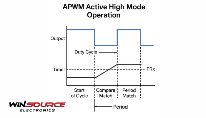
The Auxiliary PWM (APWM) mode is a feature found in some microcontrollers and peripheral modules (often tied to auxiliary timers or compare units). It allows a timer-driven output pin to generate a continuous square wave with a user-defined period and duty cycle.
Period Register (PRx) sets the full cycle length.
Compare Register (CMPx) defines the switching point within the cycle.
Together, they control how long the output stays high versus low.
2. Active High Operation
When APWM is configured as active high:
The output signal goes high at the beginning of each period (i.e., when the timer resets).
The output remains high until the timer reaches the compare match value.
At the compare match event, the output transitions low and stays low until the next timer reset.
This produces a waveform where the high portion corresponds to the duty cycle, and the low portion completes the period.
3. Timing Behavior
Start of Cycle: Timer = 0 → Output is set HIGH.
Compare Event: When Timer = CMPx → Output is cleared LOW.
Period Match: When Timer = PRx → Timer resets to 0, output immediately goes HIGH again, and a new cycle begins.
This sequence repeats indefinitely, generating a continuous pulse train.
4. Duty Cycle and Period Control
Duty cycle (D) = CMPx ÷ (PRx + 1)
Period (T) = (PRx + 1) × Timer Clock Period
High time = CMPx × Timer Clock Period
Low time = (PRx − CMPx + 1) × Timer Clock Period
Thus, by programming PRx and CMPx, the user can achieve precise control of both frequency and duty cycle.
5. Key Implications of Active High Mode
The waveform is high at the beginning of each cycle (important for external devices that expect a positive edge at cycle start).
If CMPx = 0 → duty cycle is 0% (always low).
If CMPx = PRx → duty cycle is ~100% (always high, except possibly for a single clock tick).
Active high operation is the most common because many digital loads expect a high pulse to represent the “active” phase.
Summary:
In APWM active high mode, the output pin goes HIGH at the start of each timer cycle, stays high until the compare match, then goes LOW for the remainder of the cycle. This produces a square wave with programmable duty cycle and period, controlled by the timer’s compare and period registers.
COMMENTS