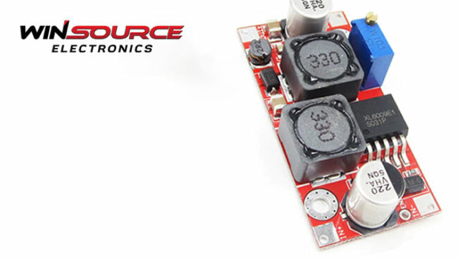
In power electronics, the buck converter is a significant player. It is renowned for transforming DC-to-DC by reducing the voltage from the source to the load, resulting in a more manageable average current draw. An alternate name for a DC boost converter is a boost converter or a DC boost chopper. Furthermore, there’s the intriguing concept of a buck-boost converter, a specialized DC-DC converter capable of delivering an output voltage that can be either higher or lower than the input voltage.
This informative article focuses squarely on exploring these three converters and shedding light on their underlying working principles.
Table of Contents
ToggleBuck converter
A buck converter, a step-down DC-to-DC power converter, is vital in managing electronic device voltage levels. It reduces the voltage from the power source to the intended load, resulting in a lower average current. This converter is a switching power supply (SMPS) type and contains essential components like semiconductors, usually a diode and a transistor.
In modern designs, a second transistor may replace the diode for synchronous rectification. Additionally, it includes an energy storage element, which could be capacitance, inductance, or a combination of both.
To ensure smooth voltage delivery, filters, often composed of capacitors paired with inductors, are commonly added to the converter’s output (the load-side filter) and input (the power-side filter). These filters are essential in reducing voltage fluctuations, creating a stable power supply.
Comparing buck converters to linear regulators, the former, as DC-DC converters, demonstrate higher efficiency. Unlike linear regulators, which achieve voltage reduction by dissipating energy as heat, buck converters are more intricate and efficient, frequently surpassing 90% efficiency. This efficiency makes them an ideal choice for converting the primary power supply voltage of computers (around 12V) to the lower voltages required by various components like USB, DRAM, and the CPU, such as 5V, 3.3V, or 1.8V, as seen in power supply units (PSUs).
The step-down DC/DC converter, commonly called the buck converter, is among the most frequently utilized DC/DC converters. It excels at reducing higher DC voltages to lower ones, such as converting from 24V to 12V or 5V. Its versatility allows it to be applied in various scenarios, offering minimal energy loss and high efficiency.
Boost converter
A DC boost converter, also known as a boost chopper, operates by increasing voltage, yielding a load voltage higher than the input power voltage. This type of DC-DC converter is a form of a switching power supply composed of essential components, including at least two semiconductor elements (a diode and a transistor) and typically an energy storage element called a boost inductor.
To minimize voltage fluctuations, capacitors (and sometimes inductors) are strategically placed at the input and output. This versatile technology finds application in various fields: automotive, power amplification, adaptive control, battery systems, consumer electronics, communication, battery charging, heating, welding, DC motor drives, power factor correction, and distributed power architecture systems.
How does it work
Controlled by a pulse width modulation (PWM) signal, the Voltage Transistor (VT) within the boost DC/DC converter functions as a rapid mechanical switch, swiftly closing and opening. When VT is switched on, the input voltage UI is directly applied to both energy storage inductor L terminals, with the freewheeling diode VD in the off state. As UI is applied to L, the inductor’s current IL experiences a linear increase, resulting in energy accumulation within the inductor. This process generates an electromotive force with positive polarity on the left side and negative polarity on the right. During this phase, the input stores magnetic field energy within the energy storage inductor L.
Concurrently, the filter capacitor C discharges, supplying current IO to the load RL. The discharge current I1 of the capacitor equals the load current IO.
Buck-Boost Converter
A buck-boost converter is a DC-DC converter capable of producing an output voltage that can be either higher or lower than the input voltage. It’s a cousin of the flyback converter, but instead of a transformer, it employs a single inductor.
Buck-boost converters come in two distinct configurations, each with a broad output voltage range from significantly higher (in absolute value) than the output voltage to nearly zero. One design is akin to a switching power supply, resembling either a buck or a boost converter, but the output voltage has the opposite polarity of the input voltage.
The duty cycle of the switching process regulates the output voltage. The other configuration is a hybrid design, ingeniously merging buck and boost converter principles.
The crucial aspect of this non-inverting converter is that the output voltage aligns with the electrical polarity of the input voltage, potentially being smaller or larger than the input value. This converter can substitute switches for diodes and efficiently share an inductor between the buck and boost sections. If you encounter a four-switch buck-boost converter, it’s essentially a four-switch version of this converter. In contrast, multiple inductors can be utilized; often, a single switch suffices, resembling the operation of a SEPIC or a UK converter.
Summary
It is clear that these converters, which discreetly make sure the proper voltage goes where it is most required, are the unsung heroes of contemporary electronics. They are the backstage magicians who expertly, efficiently, and adaptably shape our technological experience.

COMMENTS