Integrating 221111-1 board mount connector configurations within electronic devices presents a unique set of challenges. RF leakage is a critical concern in maintaining signal quality and preventing interference.
Innovative shielding solutions and advanced materials to minimize RF leakage address these challenges. Additionally, optimizing signal paths and implementing sophisticated filtering techniques are crucial for achieving optimal performance in electronic devices.
Let’s get into the details now:
Strategies for RF Leakage Control
1. Enhanced Shielding
The 221111-1 connector’s nickel-plated brass body provides a foundation for effective shielding. However, in high-frequency applications, additional measures may be necessary. Engineers can consider incorporating supplementary shielding, such as conductive gaskets or coatings, to minimize electromagnetic interference (EMI) and enhance overall shielding effectiveness.
2. Material Optimization
The choice of materials in connector construction significantly influences its RF performance. The 221111-1’s use of PTFE for dielectric and insulation materials is advantageous. PTFE is known for its low dielectric constant, which helps maintain signal integrity. Engineers may explore advanced materials with even lower dielectric constants for critical applications to further optimize.
3. Connector Design and Layout
The connectors’ orientation and arrangement on the PCB can impact RF leakage. In the case of the 221111-1 connector, its vertical orientation and through-hole mounting can aid in achieving a more controlled signal path. Engineers should carefully consider the layout and spacing of connectors to minimize crosstalk and ensure optimal signal routing.
4. Precision Termination Techniques
Proper termination is essential for preventing RF leakage. The 221111-1 connector’s solder and through-hole termination offer reliability, but precision is key. Engineers must follow best practices for soldering, ensuring a secure and uniform connection to prevent signal losses and minimize the chances of leakage.
5. Environmental Sealing
While the 221111-1 connector is not explicitly listed as sealable, environmental factors can contribute to RF leakage. In outdoor or harsh environments, moisture and contaminants may compromise the connector’s performance. Engineers should consider additional sealing techniques or enclosures to protect connectors from environmental factors that could contribute to RF leakage.
6. Frequency Band Optimization
The 221111-1 connector is optimized for a frequency of 4 GHz, making it suitable for many RF applications. However, in scenarios where higher frequencies are involved, engineers should explore connectors specifically designed for those frequencies to ensure minimal signal loss and leakage.
7. Quality Control and Testing
Implementing robust quality control measures during manufacturing ensures that each 221111-1 connector meets its specifications. Additionally, thorough testing for RF leakage at different frequencies and power levels can identify potential issues early in the production process.
How to Implement the Connector Layout Optimization
Strategic Placement for Minimal Interference
Ensuring connectors on a circuit board are strategically placed minimizes radio frequency (RF) signal leaks. Connector layout optimization is not just about randomly putting components on the board; it involves a thorough planning process.
Engineers consider the spatial relationships between connectors, focusing on how they’re oriented and how close they are to each other. By carefully organizing the layout, especially in the context of the 221111-1 board mount configuration, the potential for RF leakage is significantly diminished, fostering a more reliable communication system.
Thoughtful Spacing to Prevent Interference
The process involves more than just placing connectors; it includes considering the proper spacing between them to prevent signal interference. Engineers aim for an organized layout that prevents signals from “bleeding” into each other. This thoughtful spacing is crucial to optimizing the connector layout and contributes to maintaining a transparent and efficient signal path.
Tailoring Layout for 221111-1 Board Mount Configuration
Specifically focusing on the characteristics of the 221111-1 board mount configuration, engineers tailor the layout to the connector’s unique design. This tailored approach ensures that the connector’s potential is maximized to minimize the risk of RF leakage. The goal is to create an environment where the connectors work seamlessly together, contributing to an optimized and efficient RF communication system.
Soldering Best Practices: Mastering the Art of Connection
Precision as the Cornerstone of Effective Termination
Precision in connecting wires is paramount when it comes to RF connectors. For the 221111-1 connector, which relies on soldering, this process demands extra care. Engineers follow a set of best practices, including ensuring all solder joints are uniform and distributing heat evenly.
This artful precision isn’t just about making a strong physical connection; it’s also about minimizing the chance of losing signals. These precise soldering practices enhance the overall performance and reliability of the 221111-1 connector, especially in RF applications.
Ensuring Uniform Solder Joints
One aspect of soldering best practices is ensuring that each joint is consistent. This means that the way each wire is connected is the same across the board. Uniform solder joints contribute to the connector’s reliability and ability to withstand the demands of operational use.
Even Heat Distribution for Longevity
Proper heat distribution during soldering is another crucial element of best practices. Engineers pay close attention to how heat is applied, making sure it’s distributed evenly. This ensures a strong connection and enhances the connector’s longevity by preventing issues that might arise from uneven heating.
Rigorous Quality Control Measures: Guardians of Consistency
Step-by-Step Checks Throughout Manufacturing
Maintaining consistent RF performance in 221111-1 connectors goes beyond the design phase and extends to the manufacturing process. Rigorous quality control measures ensure that each connector meets the specified standards. Engineers and quality control personnel perform thorough checks, examining factors such as impedance, insulation resistance, and RF leakage at varying frequencies.
Identifying and Rectifying Deviations Early On
Thorough testing serves as a guardian, identifying deviations from standards early in manufacturing. This proactive approach allows for prompt rectification of any issues, ensuring that the end product is of the highest quality. Manufacturers guarantee a reliable and consistent product that performs well in diverse communication systems by catching and fixing deviations early.
High-Quality End Product Through Comprehensive Testing
The combination of stringent quality control measures and comprehensive testing results in a high-quality end product. Each connector is thoroughly vetted to ensure it meets the necessary criteria for reliable RF performance. This commitment to quality is fundamental to the success of the 221111-1 connector in various communication applications.
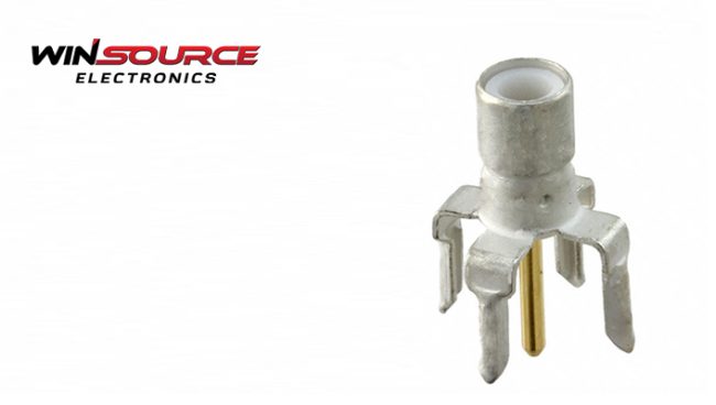
The 221111-1 board mount connector, with its brass and nickel construction, PTFE insulation, and SMB form factor, is reliable for RF applications up to 4 GHz. However, to achieve optimal performance and control RF leakage, engineers must employ a combination of enhanced shielding, material optimization, precision termination, and careful connector design.
That said, if you need high-quality RF coaxial board mount connectors, don’t hesitate to visit WIN SOURCE. A distributor with thousands of electronic components in their arsenal.
COMMENTS