* Question
How to measure the quality of a diode?
* Answer
The quality of a diode can be evaluated by measuring its electrical characteristics, junction integrity, and response under load conditions. These parameters determine whether a diode performs within its specified limits for rectification, switching, or protection functions. The measurement process typically involves both static tests and dynamic performance assessments.
1. Forward Voltage Test
This is the most fundamental diode test.
Method:
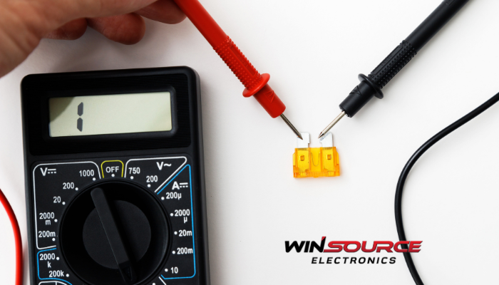
Set a multimeter to diode test mode. Connect the positive (red) probe to the anode and the negative (black) probe to the cathode.
Expected result:
A healthy silicon diode should show a forward voltage drop between 0.6 V and 0.7 V, while Schottky diodes typically range from 0.2 V to 0.4 V.
If the reading is significantly higher or lower, the diode may be degraded or faulty.
2. Reverse Leakage Test
This test checks the diode’s ability to block current in reverse bias.
Method:
Reverse the meter leads. In this configuration, a good diode should display an open-circuit or OL (over-limit) indication.
Expected result:
If the meter shows a measurable voltage or current flow, the diode exhibits excessive reverse leakage, indicating junction breakdown or contamination.
3. Reverse Breakdown Voltage (VR Test)
This test is typically performed using a curve tracer or semiconductor parameter analyzer.
Purpose:
To ensure the diode can withstand the specified reverse voltage without permanent damage.
Expected result:
The measured breakdown voltage should match or exceed the rated VR value stated in the datasheet.
A lower-than-expected breakdown voltage often signals junction defects or manufacturing degradation.
4. Reverse Recovery Time (trr) Test
For switching diodes or rectifiers used in high-speed applications, measuring reverse recovery time is critical.
Method:
Apply a pulsed current waveform and measure how long the diode takes to stop conducting when polarity reverses.
Expected result:
A smaller trr value indicates faster switching and better performance.
Long recovery times suggest excess charge storage or material defects.
5. Forward Current vs. Voltage (I-V Curve) Analysis
Plotting the I–V characteristics provides a complete view of diode behavior.
Healthy diode curve:
Shows a smooth exponential rise in forward bias and near-zero current in reverse bias.
Abnormal patterns:
Irregular slopes, premature breakdown, or leakage tails imply defective junctions or thermal stress damage.
6. Visual and Thermal Inspection
High-quality diodes should also be evaluated for:
Package integrity (no cracks or discoloration)
Consistent solderability
Stable junction temperature performance under rated current loads
Infrared thermography or thermal imaging can help detect localized heating or bonding defects.
Conclusion
To accurately measure diode quality, engineers must combine electrical tests (forward/reverse bias, leakage, breakdown) with dynamic analysis (reverse recovery, I–V curves). A diode that meets its datasheet parameters under these tests is considered reliable for use in power conversion, signal rectification, or protection circuits.
COMMENTS