* Question
What Are the Important Parameters in Serial Communication?
* Answer
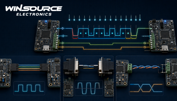
Serial communication transfers data sequentially over one or more signal lines. For reliable communication, the transmitter and receiver must use compatible electrical interfaces, timing settings, and data-frame formats. The exact parameters depend on the protocol, such as UART, RS-232, RS-485, SPI, or I²C.
Baud Rate
The baud rate specifies the number of signal symbols transmitted per second. Common UART rates include 9,600, 115,200, and 1,000,000 baud. In simple binary UART communication, one symbol normally carries one bit, so baud rate and raw bit rate are numerically equal. Both devices must use matching rates within the timing tolerance permitted by their clock accuracy.
Data Bits
This setting defines the number of payload bits in each UART character. Values typically range from five to nine bits, with eight data bits being the most common. The selected word length must match at both ends of the connection.
Parity
A parity bit provides basic error detection. Common options include:
- None
- Even parity
- Odd parity
- Mark or space parity
Parity can detect some single-bit errors, but it does not replace stronger methods such as checksums or cyclic redundancy checks.
Stop Bits
Stop bits identify the end of an asynchronous data frame and allow the receiver to resynchronize. UART interfaces commonly use one, one-and-a-half, or two stop bits. More stop bits increase timing margin but reduce effective throughput.
A UART configuration is often written as 115200, 8N1, meaning 115,200 baud, eight data bits, no parity, and one stop bit.
Flow Control
Flow control prevents a fast transmitter from overwhelming the receiver. It may be implemented using hardware signals such as RTS/CTS or software characters such as XON/XOFF. Some embedded links operate without flow control when the receiver can always process incoming data fast enough.
Electrical Interface
Logic levels and physical-layer requirements must also be compatible. TTL/CMOS UART, RS-232, and RS-485 use different voltage levels and signaling methods. RS-485 additionally requires correct differential termination, biasing, topology, and transceiver direction control. Connecting incompatible interfaces directly may cause communication failure or component damage.
Additional Design Parameters
Engineers should also consider:
- Synchronous or asynchronous operation
- Clock polarity and phase for SPI
- Device addresses for I²C or multidrop networks
- Full-duplex, half-duplex, or simplex operation
- Cable length, termination, grounding, and noise immunity
- Connector pinout and signal polarity
- Packet structure, byte order, timeouts, and error checking
- Required payload throughput and communication latency
When selecting components, verify the supported protocols, maximum data rate, supply voltage, logic-level thresholds, buffer capacity, isolation requirements, ESD protection, and operating temperature. Matching only the baud rate is insufficient; the complete frame format, electrical standard, and higher-level data protocol must be compatible.