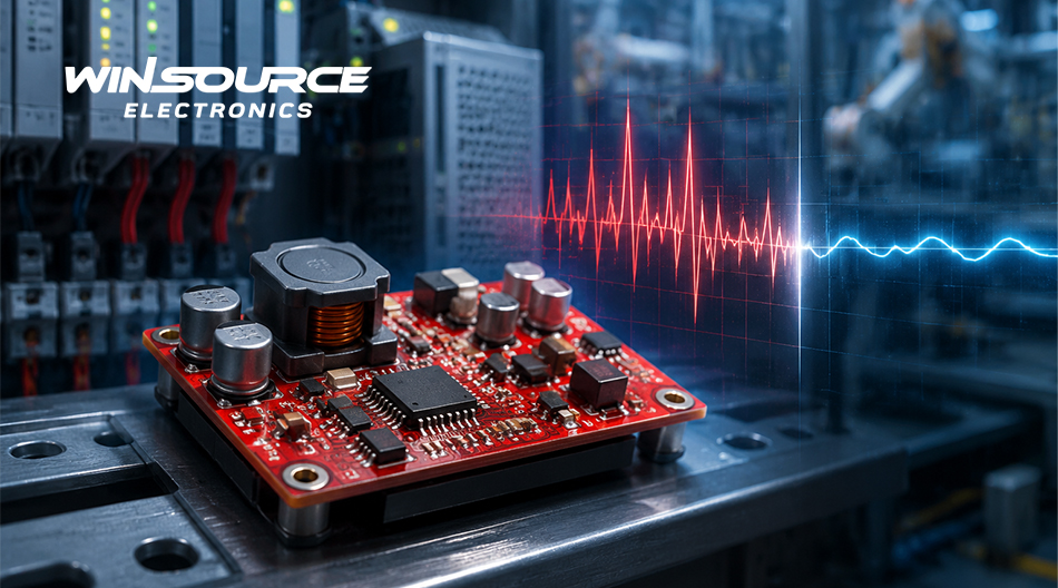
In industrial control systems, PLCs, sensors, and communication equipment, a 24V bus does not always remain at its nominal level. Long cable runs, load switching, and the turn-off of inductive devices can all introduce voltage fluctuations, making adequate input headroom an important design consideration. A 42V-input buck converter provides a wider operating margin for these variations and any residual transients after protection, but it must still be supported by proper surge suppression, thermal design, and load assessment rather than treated as a substitute for system-level protection.
1. A Nominal 24V System Can Still Experience Higher Input Voltages
Industrial power supplies typically allow a certain output tolerance, while the bus voltage may also be affected by cable impedance, grounding conditions, and load changes. When relays, solenoid valves, motors, or other inductive loads switch rapidly, stored energy in the wiring can generate short-duration voltage spikes. Parasitic inductance in long cables and distributed wiring further increases the difficulty of transient control.
If the converter’s maximum operating input is too close to the normal system voltage, even localized fluctuations can reduce design margin while the average input remains within the specified range. A 42V operating range expands the available margin, but the input stage should still include appropriate protection such as a TVS diode, filtering network, fuse, or reverse-polarity protection. Converter voltage capability and system-level protection address different design requirements.
2. A 42V Operating Range Provides Practical Design Margin
The selection of a high-voltage buck converter should not be based solely on the nominal system voltage. The recommended operating range and the absolute maximum rating must both be considered. The recommended operating range defines the conditions under which the device can operate continuously, while the absolute maximum rating represents a limit that should not be used as a normal design target.
For a 24V industrial power system, the TPS54340DDAR supports an operating input range of 4.5V to 42V and can deliver up to 3.5A of continuous output current. This wide input range can accommodate common 12V and 24V power buses while providing margin for supply tolerance and a certain degree of line variation.
This voltage margin does not eliminate the need for system-level protection. If unsuppressed transients may exceed the allowable device range, the voltage at the VIN pin must still be limited through TVS clamping, input filtering, or upstream protection. The design should then be verified under worst-case operating conditions.
3. Efficiency and Thermal Performance Must Also Be Evaluated
In applications that convert 24V to 5V, 3.3V, or a lower voltage, the large input-to-output voltage difference can increase losses in the switching device, catch diode, and inductor. Efficiency and temperature rise also depend on load current, switching frequency, component parameters, and PCB thermal design. They cannot be assessed from input voltage and rated output current alone.
An adjustable switching-frequency range of 100kHz to 2.5MHz provides flexibility when balancing efficiency, component size, and EMI performance. A lower frequency can reduce some switching losses, while a higher frequency may allow the use of smaller inductors and capacitors. However, higher frequency can also increase thermal stress and high-frequency noise. External clock synchronization can support system-level frequency planning and help reduce interference between multiple switching converters.
A thermally enhanced HSOIC package with PowerPAD helps transfer heat into the PCB. The exposed pad should be properly soldered and connected to an adequate ground-copper area with suitable thermal vias. The input bypass capacitor should be placed close to VIN and GND, while the SW node and high-frequency current loops should be kept as short as practical. Final thermal performance must still be verified under the actual load, ambient-temperature, and PCB-layout conditions.
4. Suitable Applications in 24V Industrial Systems
A wide input range, adjustable switching frequency, and integrated protection functions make this class of converter suitable for industrial power nodes with variable input conditions and changing load profiles. Adjustable undervoltage lockout and hysteresis help define controlled startup and shutdown thresholds. Cycle-by-cycle current limiting, thermal shutdown, frequency foldback, and soft start provide basic protection under abnormal conditions. Eco-mode operation can also reduce light-load losses in equipment with standby or intermittent operating states.
Typical applications include:
- 24V-to-5V or 24V-to-3.3V industrial control-board power supplies;
- PLCs, remote I/O modules, and sensor-interface modules;
- Auxiliary power rails for communication equipment and embedded control units;
- Platform designs that must support both 12V and 24V buses.
The main value of a 42V operating input range is the additional margin it provides once the system voltage boundaries have been clearly defined. With 3.5A output capability, adjustable switching frequency, and multiple protection functions, the TPS54340DDAR can be considered for a range of 24V industrial power applications. Final device selection should still be based on input transients, load profiles, thermal conditions, and external-component requirements. WIN SOURCE can provide product specifications, availability information, and sourcing references to support engineering and procurement evaluation.
© 2026 Win Source Electronics. All rights reserved. This content is protected by copyright and may not be reproduced, distributed, transmitted, cached or otherwise used, except with the prior written permission of Win Source Electronics.