* Question
What are the message frame formats in CAN 2.0B?
* Answer
The CAN 2.0B protocol, defined under ISO 11898, supports robust, real-time communication in distributed control systems. It introduces two primary message frame formats—Standard Frame and Extended Frame—distinguished by the length of their identifier field. Each format supports multiple frame types, enabling flexible communication between devices on a CAN network.
Table of Contents
Toggle1. Frame Format Classification
A. Standard Frame Format
Identifier Length: 11 bits
Also Known As: CAN 2.0A frame
Structure: Designed for smaller networks where fewer message identifiers are sufficient.
Compatibility: Supported by both CAN 2.0A and 2.0B controllers.
B. Extended Frame Format
Identifier Length: 29 bits
Structure: Uses the base 11-bit ID + an 18-bit extension.
Compatibility: Only fully supported by CAN 2.0B controllers.
2. Frame Types in CAN 2.0B
Both Standard and Extended formats support four types of frames:
a. Data Frame
Purpose: Transmits actual data (up to 8 bytes).
Contains: Identifier, Data Length Code (DLC), Data Field.
b. Remote Frame
Purpose: Requests data from another node.
Difference: Identical to a data frame but without the data field; the RTR (Remote Transmission Request) bit is set.
c. Error Frame
Purpose: Sent when a node detects a bus error.
Composition: 6–12 dominant bits (Error Flag) followed by an Error Delimiter.
d. Overload Frame
Purpose: Used to delay the next data frame; typically sent when a node is not ready to receive more data.
Structure: Similar to error frame (two fields: overload flag and overload delimiter).
3. Standard vs Extended Frame Structure
Below is a simplified comparison of Standard and Extended Data Frame formats:
Standard Data Frame (11-bit ID)
Field | Description |
SOF (1 bit) | Start of Frame |
Identifier (11 bits) | Message arbitration ID |
RTR (1 bit) | Remote transmission request (dominant = data frame) |
IDE (1 bit) | Identifier Extension (dominant = standard) |
r0 (1 bit) | Reserved bit |
DLC (4 bits) | Data Length Code (0–8 bytes) |
Data Field (0–8 bytes) | Actual payload |
CRC (15 bits + delim) | Error checking |
ACK (2 bits) | Acknowledgement slot and delimiter |
EOF (7 bits) | End of Frame |
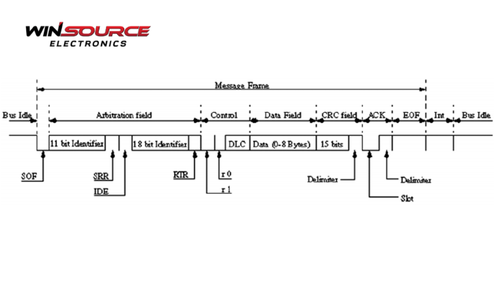
Extended Data Frame (29-bit ID)
Field | Description |
SOF (1 bit) | Start of Frame |
Base ID (11 bits) | Standard identifier |
SRR (1 bit) | Substitute Remote Request |
IDE (1 bit) | Identifier Extension (recessive = extended) |
Extended ID (18 bits) | Additional identifier bits |
RTR (1 bit) | Remote request indicator |
r1, r0 (2 bits) | Reserved bits |
DLC (4 bits) | Data Length Code |
Data Field (0–8 bytes) | Payload |
CRC (15 bits + delim) | Error detection |
ACK (2 bits) | Acknowledgement |
EOF (7 bits) | End of Frame |
4. Interframe Space
All CAN messages are separated by an interframe space, a minimum 3-bit recessive field, ensuring clear delineation between consecutive frames. This helps in bus synchronization and error recovery.
Insight
CAN 2.0B’s dual-frame format structure offers scalability—allowing systems to start with standard frames and later expand to extended identifiers without overhauling the network. The consistent structure, built-in arbitration, and error detection mechanisms make CAN 2.0B a preferred protocol in automotive, industrial automation, and medical device communication.
COMMENTS