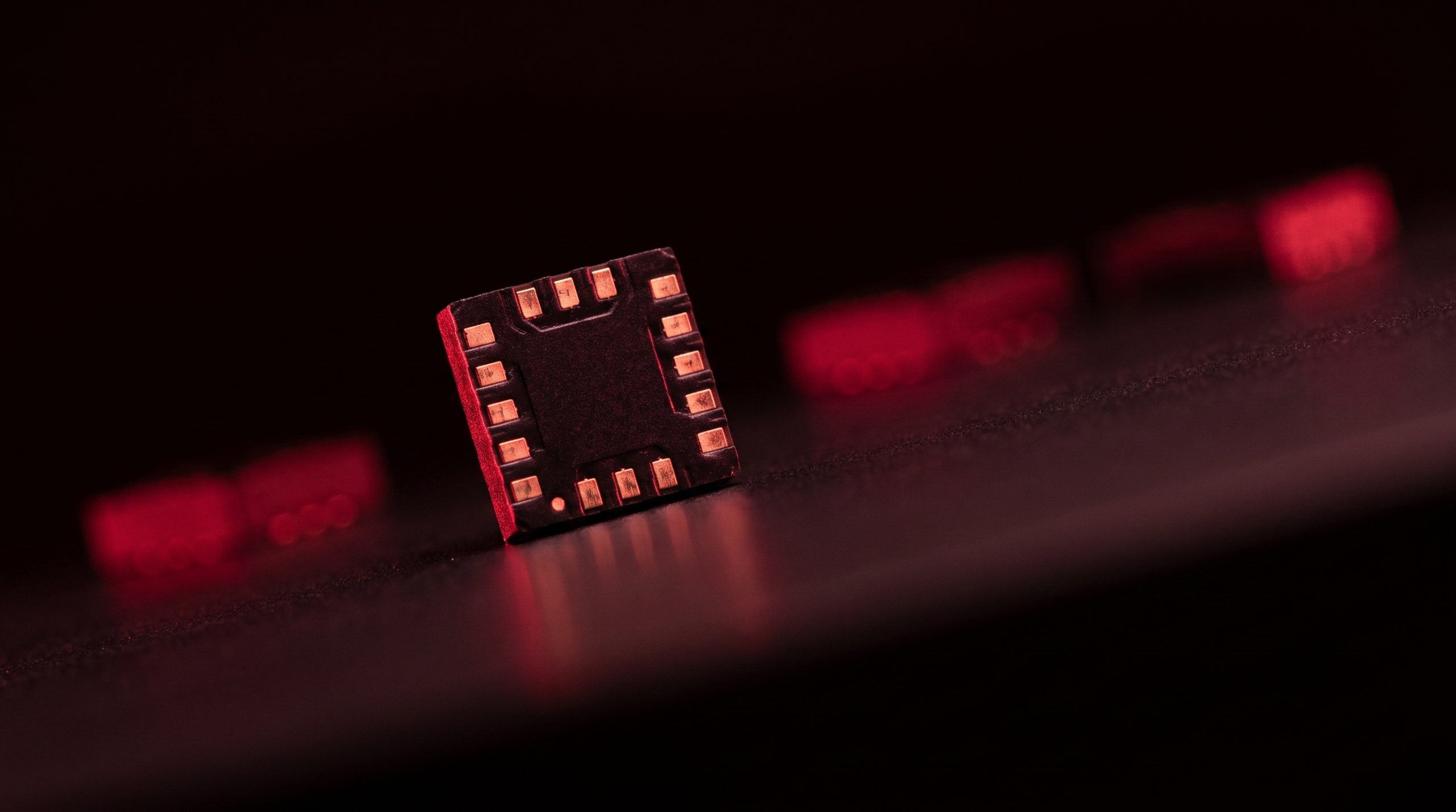
Accelerometers are among the most widely deployed sensors in modern electronics. They appear in automotive safety systems that trigger airbags, in industrial machines that monitor bearing health, in the smartphones that detect screen orientation, and in aerospace inertial navigation units that must not fail. Despite being a mature technology, accelerometers remain an active sourcing challenge — especially as specific devices reach end-of-life (EOL) while the equipment they power continues operating for years or decades.
This article covers the core accelerometer sensor types, how each sensing technology works and where it fits best, the output interfaces designers encounter on real components, and what procurement teams need to know when a preferred part goes obsolete. Whether you are selecting an accelerometer for a new design or trying to keep an existing product running after a PCN arrives, the sections below provide the technical grounding to make informed decisions.
What Is an Accelerometer Sensor?
An accelerometer is a transducer that converts a mechanical acceleration input into a proportional electrical signal output. The operating principle in virtually all practical designs relies on Newton’s second law: a proof mass (or seismic mass) suspended within the sensor package experiences a force when the device accelerates, and that force is measured through changes in charge, capacitance, resistance, or another physical property. The resulting electrical signal is then conditioned, amplified, and made available to a host system through one of several interface types.
Accelerometers are used across a remarkably wide range of industries and applications. Automotive engineers rely on them for crash-detection and rollover sensing. Industrial maintenance teams use them for vibration-based condition monitoring of rotating machinery. Consumer electronics designers integrate them for gesture recognition, step counting, and display orientation. Aerospace and defense programs use high-performance versions for inertial navigation. The diversity of applications explains why the accelerometer market includes dozens of different sensing technologies, dynamic ranges, and interface standards — each optimized for a different set of requirements.
AC-Response vs. DC-Response Accelerometers
The most fundamental distinction in accelerometer behavior is whether the sensor can respond to static (zero-frequency) inputs or only to dynamic ones. An AC-response accelerometer has an AC-coupled output, which means its internal RC time constant acts as a high-pass filter. The sensor cannot track a steady state acceleration such as gravity, a sustained tilt, or a slow centrifugal force. It is inherently suited to measuring vibration and other dynamic events.
A DC-response accelerometer, by contrast, has a DC-coupled output and can follow acceleration signals all the way down to 0 Hz. This makes it the appropriate choice whenever static or quasi-static accelerations matter, and it is also the correct choice whenever velocity or displacement are to be derived from acceleration by integration. Integrating an AC-coupled signal introduces a growing error because the sensor cannot accurately track the slowly changing components of the input — a problem that becomes severe for any real-world signal that is not a clean high-frequency transient. Both capacitive MEMS and piezoresistive accelerometers fall into the DC-response category, while traditional piezoelectric accelerometers are AC-response devices.
Sensing Technologies Explained
Piezoelectric Accelerometers
Piezoelectric (PE) accelerometers use a crystal or ceramic element — most commonly lead zirconate titanate (PZT) — that generates an electric charge when mechanically stressed. When the proof mass presses against the piezoelectric material under acceleration, the resulting charge or voltage is proportional to that acceleration. Because the piezoelectric element behaves electrically like a high-impedance capacitor, the signal requires careful conditioning. There are two main output variants: charge-output types, which require an external charge amplifier and low-noise coaxial cable, and voltage-output (IEPE) types, which contain an internal charge amplifier and use a simpler two-wire coaxial connection.
The primary strength of piezoelectric accelerometers is their exceptional frequency range — useful bandwidth can extend well above 10 kHz — combined with wide operating temperature ranges. Charge-output variants rated for use from below -100°C to above 300°C are available, making them standard in turbine engine monitoring and extreme-temperature structural testing. The fundamental limitation is that they are AC-coupled and therefore unsuitable for static or very-low-frequency measurements.
Capacitive (MEMS) Accelerometers
Capacitive accelerometers measure acceleration through changes in capacitance between a movable proof mass and fixed electrodes. When the sensor accelerates, the proof mass shifts relative to the fixed plates, changing the gap and therefore the capacitance. An on-chip detection circuit converts this capacitance change into an output signal. The technology is closely associated with MEMS (Micro-Electro-Mechanical Systems) fabrication, which allows the mechanical structure and interface circuitry to be integrated on a single silicon die at very low cost.
Capacitive MEMS accelerometers are DC-response devices with good linearity and stability, making them the dominant choice for consumer electronics, automotive safety systems, and low-to-moderate-frequency industrial sensing. Their working bandwidth is generally limited to a few hundred hertz, and their full-scale range tends to top out around ±200g for most general-purpose devices, though the majority of consumer-grade parts cover ±2g to ±16g. Power consumption is typically in the low-microamp to low-milliamp range, which is attractive for battery-operated applications. The trade-off is a higher noise floor compared to a well-implemented piezoresistive design, and sensitivity to the internal clock frequency used by the detection circuit.
Piezoresistive Accelerometers
Piezoresistive (PR) accelerometers use resistive strain elements — essentially miniaturized strain gauges — whose resistance changes when the proof mass flexes the supporting beams under acceleration. The output is a differential resistance signal that can be read directly as a Wheatstone-bridge voltage. Because the output is a pure resistance change, the signal-to-noise ratio can be very high, and the full-scale range can extend to tens of thousands of g — making piezoresistive sensors the standard choice for high-shock testing such as automotive crash analysis, weapons testing, and high-g impact events.
Piezoresistive accelerometers are DC-response devices with a working bandwidth that can reach 5000 Hz or beyond. Many designs use air or fluid damping to prevent resonance during high-frequency events, which is an important consideration when the input contains significant energy above the sensor’s natural frequency. The main practical limitation is temperature sensitivity: the resistance elements change value with temperature, so on-chip or external temperature compensation is usually necessary for accurate measurement across a wide thermal range.
Output Interfaces and Signal Types
Understanding a sensor’s transduction technology tells you how it measures acceleration internally. What matters for system integration is how it delivers that measurement to a host processor or data acquisition system. Accelerometers offer several distinct interface types, each with its own trade-offs in noise immunity, integration complexity, and feature richness.
Analog Output
Analog-output accelerometers produce a continuously varying voltage proportional to acceleration — typically ratiometric with the supply voltage. The output connects directly to a microcontroller ADC or to a data acquisition front end. The main appeal is simplicity and low latency: there is no communication protocol overhead, and the designer retains full control over bandwidth, filtering, and gain selection by choosing external components. The Analog Devices ADXL335, for example, allows the user to set accelerometer bandwidth per axis using external capacitors, covering the range from 0.5 Hz to 1600 Hz on the X and Y axes. The disadvantage is susceptibility to noise from PCB layout, power supply, and cable impedance, which must be managed carefully in the analog signal path.
Digital Output: I2C and SPI
Most modern MEMS accelerometers offer digital output via I2C (Inter-Integrated Circuit) or SPI (Serial Peripheral Interface). Both protocols carry acceleration data as formatted digital words over a two-wire or four-wire bus, connecting directly to a microcontroller without requiring an external ADC. Digital accelerometers tend to be less susceptible to analog noise than their analog counterparts, and they offer a much richer feature set: configurable full-scale ranges, programmable output data rates, on-chip FIFO buffers, interrupt outputs for event detection (tap, freefall, activity/inactivity), and self-test modes.
The practical distinction between I2C and SPI matters at higher data rates. I2C is a multi-device bus well suited to simple, lower-rate applications — typical clock speeds top out at 400 kHz in fast mode. SPI is point-to-point but runs significantly faster, making it the better choice when the application requires high output data rates or when the accelerometer shares a bus with other high-speed peripherals. Many devices support both protocols and let the designer select via a hardware pin.
PWM Output
Some accelerometers — particularly older designs — provide a pulse-width modulation (PWM) output, where acceleration is encoded as the duty cycle of a square wave with a fixed period. PWM sensors are relatively straightforward to decode with a timer peripheral on most microcontrollers, but they are less common in current designs. They occupy a middle ground: simpler to decode than a serial digital interface, but offering none of the advanced configuration features that I2C and SPI devices provide.
Single-Axis, Dual-Axis, and Tri-Axis Configurations
Accelerometers are available in single-axis, dual-axis, and tri-axis (three-axis) configurations. Single-axis devices sense acceleration along one defined measurement axis and are typically used in applications where only one direction matters — certain industrial vibration probes, for instance. Dual-axis devices cover two axes and are sometimes found in automotive tilt applications. For the vast majority of modern applications, however, tri-axis devices have become the default. They measure acceleration simultaneously in the X, Y, and Z directions, enabling full three-dimensional motion and orientation sensing in a single compact package.
Tri-axis sensors can be implemented using three orthogonally mounted single-axis sensing elements, or using a single proof mass designed to respond to out-of-plane as well as in-plane motion. Monolithic integration of all three axes in a single MEMS structure reduces device footprint and eliminates axis misalignment errors that arise when separate single-axis devices are stacked. Tri-axis parts have also become the volume mainstream of the category, which is what makes them the practical default for new designs regardless of whether all three axes are actively used.
Common Accelerometer ICs and Their Characteristics
A handful of accelerometer ICs have seen particularly broad deployment across industries, and they appear frequently in both active BOM management and EOL sourcing discussions.
The ADXL345 from Analog Devices is a low-power three-axis accelerometer with up to 13-bit resolution and I2C or SPI digital output. It supports selectable full-scale ranges of ±2g, ±4g, ±8g, and ±16g, and includes built-in tap detection, freefall detection, and activity/inactivity sensing. Its combination of high resolution, low power (as low as 23 µA in measurement mode), and flexible interface has made it a long-running choice for portable devices, IoT nodes, wearables, and embedded industrial designs.
The LIS3DH from STMicroelectronics is a tri-axis accelerometer known for ultra-low power consumption, making it particularly attractive for battery-powered wearables and IoT applications where sleep current matters. It supports I2C and SPI output, selectable ranges from ±2g to ±16g, output data rates spanning 1 Hz to 5.3 kHz, a 32-level FIFO buffer, and programmable interrupt generators. The LIS3DH’s wide operating temperature range and durable design also support automotive diagnostics and outdoor industrial environments.
The MPU-6050 from InvenSense (now TDK) combines a three-axis MEMS accelerometer and a three-axis MEMS gyroscope on a single chip with a 16-bit ADC for each channel, communicating over I2C. Its built-in Digital Motion Processor (DMP) can offload sensor fusion calculations from the host processor. The MPU-6050 has been widely used in drone flight controllers, self-balancing robots, gaming controllers, and motion-capture systems where both linear acceleration and angular velocity are needed simultaneously.
Other widely referenced devices include the Analog Devices ADXL335 (analog output, low power, popular in cost-sensitive designs), the STMicroelectronics LIS344AL (an analog three-axis MEMS accelerometer that still turns up in legacy designs), and various high-g piezoresistive devices from manufacturers such as Kistler and PCB Piezotronics for shock and crash testing.
Matching Sensor Type to Application
Choosing the right accelerometer requires aligning the sensor’s performance characteristics with what the application actually demands. A few guiding principles are worth keeping in mind.
For consumer and mobile electronics — smartphones, wearables, fitness trackers, gaming peripherals — capacitive MEMS devices with digital I2C or SPI output dominate almost entirely. Low cost, small footprint, low power, and adequate dynamic range (typically ±2g to ±8g) cover these requirements well. Battery life constraints make ultra-low-power modes and intelligent interrupt outputs particularly valuable here.
For industrial condition monitoring and vibration analysis, the requirements depend heavily on frequency content. Low-frequency machine health monitoring (conveyor systems, pump monitoring) can use capacitive MEMS devices. Higher-frequency vibration signatures from motors and bearings often require piezoelectric IEPE sensors with wider bandwidth and better high-frequency fidelity. The specific frequency range, dynamic range, and environmental temperature drive the choice.
For automotive safety applications such as airbag deployment, capacitive MEMS sensors have become standard. The need for DC response (detecting the sustained deceleration of a crash), low cost at volume, and reliability under automotive environmental conditions all favor MEMS capacitive designs.
For shock, impact, and crash testing — automotive safety certification, weapons testing, drop testing — piezoresistive sensors are typically the right answer. Their high full-scale range (up to tens of thousands of g), DC response, and wide bandwidth make them the correct tool where both frequency content and amplitude can be extreme simultaneously.
Sourcing EOL and Obsolete Accelerometer Parts
Component obsolescence is a structural reality of the electronics industry, and accelerometer sensors are not immune. Semiconductor manufacturers discontinue parts for a range of reasons: declining demand for a particular generation of sensors, technology migration to newer architectures, fab node consolidation, or the simple commercial decision that a product no longer merits continued production. EOL notices are often issued with limited lead time, leaving procurement and engineering teams with three options: execute a last-time buy, qualify a functional equivalent or alternate, or redesign the affected board.
The timing mismatch between component lifecycles and product lifecycles is a significant source of supply-chain risk. Industrial systems, medical equipment, aerospace platforms, and defense hardware routinely carry service obligations of ten, twenty, or more years — far longer than the five-to-ten-year production window typical for many sensor ICs. A specific accelerometer part that was designed into a product in 2010 may have reached EOL status years ago, while the end product is still being manufactured or serviced. Once a part is discontinued the manufacturer no longer produces it, and whatever remains is spread across the wider supply base, where it has to be located and verified.
Effective obsolescence management starts before a PCN arrives, not after. Monitoring lifecycle status for every critical sensor in a BOM, tracking Product Change Notifications from manufacturers, and modeling forward inventory needs based on production forecasts are all practices that create lead time for response. When a part does reach EOL, the options available narrow quickly as remaining stock is consumed: the window for a cost-effective last-time buy closes, equivalent alternates may require re-qualification, and redesign carries both engineering cost and schedule risk. Whichever alternate a cross-reference turns up, final approval belongs to the customer’s engineering team — a parametric match is necessary but not sufficient, because package, pinout, temperature grade and qualification level all have to hold as well.
A supply-chain partner earns its place across the whole of a product life measured in decades: supplying parts that are in current production, locating verified stock of parts that are no longer made, running cross-references when no direct stock exists, and keeping lifecycle status visible across the BOM throughout. The value of that comes from engaging it before a constraint bites rather than after.
WIN SOURCE is a global independent distributor of electronic components, supporting component supply, shortage sourcing, lifecycle management and alternative solutions. Its catalog covers motion sensors and accelerometers from manufacturers including Analog Devices, STMicroelectronics and TDK/InvenSense, spanning both active production parts and end-of-life components.
When evaluating any source for EOL accelerometer parts, the core verification requirements are consistent: demand full traceability documentation (date codes, country of origin, manufacturer documentation), require a Certificate of Conformance, and apply incoming inspection protocols appropriate to the application’s risk level. Counterfeit risk is real wherever traceability is thin, and the consequences of a fraudulent sensor in a safety-critical system are severe. Quality certifications such as AS9120 and ISO 9001, together with a documented incoming-inspection procedure and a published return policy, are what let you judge how a given supplier controls that risk rather than having to take it on trust.
Summary
Accelerometers span a wide range of technologies, each with a distinct set of strengths. Piezoelectric sensors offer exceptional bandwidth and temperature range for dynamic, high-frequency measurements. Capacitive MEMS devices provide the DC response, low power, and cost efficiency that dominate consumer and automotive applications. Piezoresistive sensors deliver the high-g range and signal quality needed for shock and impact testing. On top of the sensing technology, the output interface — analog, I2C, SPI, or PWM — determines how the sensor integrates into a system and what configuration and feature options are available.
Selecting the right accelerometer means matching these technical parameters to the application’s actual requirements: frequency range, dynamic range, static vs. dynamic response, axis count, power budget, and operating environment. For most new designs with moderate performance requirements, a tri-axis digital MEMS accelerometer with I2C or SPI output will be the pragmatic starting point. For teams managing long-life products, the EOL dimension is equally important — building a proactive obsolescence strategy around key sensor components is as much a part of sound design practice as getting the initial specification right.
Frequently Asked Questions
What is the difference between an AC-response and a DC-response accelerometer?
A DC-response accelerometer can measure acceleration all the way down to 0 Hz, so it registers gravity, tilt and sustained acceleration; an AC-response accelerometer is high-pass filtered and only sees changing inputs. Capacitive MEMS and piezoresistive devices are DC-response; traditional piezoelectric devices are AC-response. If you need static measurement, or you plan to integrate acceleration to get velocity or displacement, you need a DC-response part.
Which accelerometer type suits vibration monitoring?
It depends on the frequency content you care about. Low-frequency machine health monitoring, such as conveyors and pumps, is well served by capacitive MEMS devices. Higher-frequency signatures from motors and bearings usually call for a piezoelectric IEPE sensor, which offers wider bandwidth and better high-frequency fidelity. Confirm the required frequency range and dynamic range against the candidate part’s datasheet before committing.
Should I choose an analog or a digital accelerometer output?
For most new designs, a digital I2C or SPI part is the pragmatic default: no external ADC, better noise immunity, and configurable ranges, data rates, FIFOs and interrupts. Analog output still makes sense when you want the lowest possible latency, full control of the filtering, or a drop-in replacement for an existing analog signal chain. SPI is the better digital choice when output data rates are high.
What happens when an accelerometer reaches end-of-life?
The manufacturer issues a PCN or discontinuance notice, usually with a last-time-buy window, and then stops production. From that point the three options are a last-time buy sized against your forward production forecast, qualification of a functional alternate, or a board redesign. Final approval of any alternate belongs to your engineering team, since a parametric match does not guarantee that package, pinout, temperature grade and qualification level all carry over.
How do I verify an obsolete accelerometer before it goes into a build?
Ask for traceability documentation, including date codes, country of origin and any manufacturer paperwork, and a Certificate of Conformance. Then check what incoming inspection the supplier applies and how it is matched to the risk of the material, and confirm what the return policy and warranty actually cover. For safety-critical hardware it is reasonable to specify the inspection level you require as part of the purchase order.
Part discontinued, obsolete or hard to find?
WIN SOURCE is a global independent distributor of electronic components, supporting component supply, shortage sourcing, lifecycle management and alternative solutions. Visual inspection, non-destructive testing and electrical testing are applied according to material risk, customer requirements and the applicable quality process, and orders are covered by the published return policy and a 3-year warranty on eligible components.
Stock and pricing are updated daily — search a part number or contact us for current availability, lead time and a quote.
© 2026 Win Source Electronics. All rights reserved. This content is protected by copyright and may not be reproduced, distributed, transmitted, cached, or otherwise used without the prior written permission of Win Source Electronics.