Look closely at any modern PCB — a USB port line, a switching power supply output, a mixed-signal ADC supply rail — and you will almost certainly find a small, often unmarked passive component sitting in series with the conductor. That component is a ferrite bead, and its job is straightforward: stop high-frequency noise from traveling where it does not belong. Despite that simplicity, the ferrite bead is one of the most misunderstood and misapplied components in circuit design. Engineers drop them onto power rails almost reflexively, sometimes solving problems, sometimes creating new ones.
This article explains what a ferrite bead actually is, the physics that make it work, and the five key parameters you need to check before committing one to a layout. By the end, you will have a clear framework for selecting a bead that does its job without introducing resonance issues, excessive voltage drop, or signal distortion.
What Is a Ferrite Bead?
A ferrite bead is a passive electronic component designed to suppress high-frequency noise on a power supply line or a signal line. Physically, it looks like a small inductor — and in many packages, it is essentially a conductor wound through or around a ferrite core. The ferrite material itself is a magnetic ceramic compound, typically iron oxide combined with zinc, nickel, or manganese oxides. These compositions give the material high magnetic permeability while keeping electrical resistivity high, which is the property combination that makes noise suppression possible.
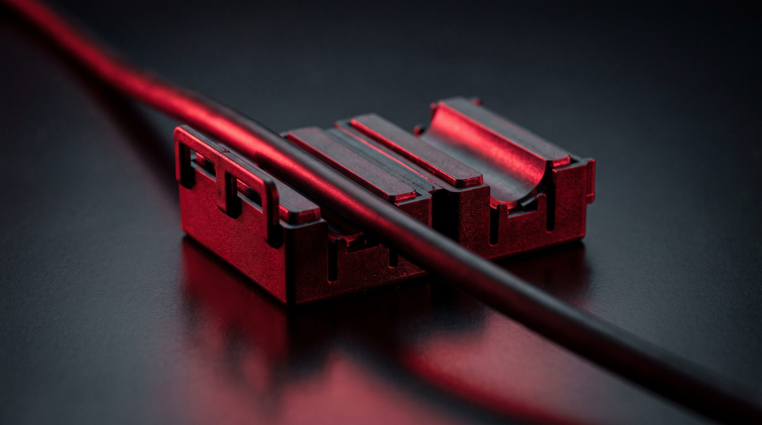
You will encounter ferrite beads in several physical forms: tiny SMD chip beads (the most common in modern PCB design), through-hole axial bead components, and the familiar clamp-on cylinders found on laptop power cables and USB cords. All of them operate on the same electromagnetic principle — they just serve different current ratings and mounting contexts. Despite resembling a simple inductor in a circuit schematic, a ferrite bead behaves quite differently at high frequencies, and that distinction is the whole point.
How a Ferrite Bead Suppresses EMI
Electromagnetic interference (EMI) is unwanted electrical noise that travels through conductors or radiates through space. In electronic systems, it originates from switching regulators, digital clock signals, fast logic transitions, and external sources — and it can degrade performance, corrupt data, or cause a device to fail regulatory compliance testing.
The mechanism by which a ferrite bead addresses conducted EMI is what sets it apart from a standard inductor. At low frequencies, the bead behaves inductively — it stores energy in a magnetic field and releases it, much like a conventional inductor, with very little loss. At high frequencies, the ferrite material’s magnetic losses increase dramatically. The component transitions from being a reactive (energy-storing) element into a resistive one. This means it no longer bounces high-frequency energy back toward the source the way an ideal inductor would; instead, it converts that energy into a small amount of heat and dissipates it. The noise is absorbed, not reflected. That is the key physical distinction: a ferrite bead kills high-frequency noise by turning it into heat, rather than redirecting it.
The practical consequence is significant. A reflected noise signal (as you would get from a high-Q inductor) can still cause interference elsewhere in the circuit. An absorbed signal is simply gone. This is why ferrite beads are preferred over standard inductors for EMI suppression work, particularly in the 10 MHz to 1 GHz range where most conducted EMI problems live.
The Three Frequency Regions of a Ferrite Bead
To select a ferrite bead correctly, it helps to understand how its behavior changes across frequency. Engineers typically represent this with a ZRX plot — a graph that charts the total impedance (Z), resistive component (R), and reactive component (X) against frequency on a single set of axes. Three distinct regions emerge from this plot, and each one has different implications for circuit design.
- Inductive region (below roughly 10–30 MHz): In this range, reactive (inductive) impedance dominates. The bead acts like a conventional inductor with a relatively high Q-factor and dissipates very little energy. If your noise problem sits here, a ferrite bead is not your best tool — and pairing it with decoupling capacitors in this region risks creating an LC resonance that can amplify noise rather than suppress it.
- Resistive region (around the self-resonant frequency, or SRF): This is where the ferrite bead does its real work. The resistive component overtakes the reactive component, losses dominate, and high-frequency noise energy is dissipated as heat. For EMI suppression, your target noise frequencies should fall within this region for maximum effectiveness.
- Capacitive region (above the SRF): Parasitic capacitance within the bead structure takes over. Impedance falls, and the component becomes increasingly transparent to very high-frequency signals. Beads operating in this region provide little or no suppression.
Most datasheets specify impedance at 100 MHz as a headline figure, but the ZRX plot tells the complete story. Checking the full curve — not just the single-frequency rating — is essential for matching a bead to your actual noise spectrum.
Types of Ferrite Beads
Ferrite beads come in several physical formats, each suited to different applications and assembly methods. Understanding the differences helps narrow the selection early in the design process.
- SMD chip beads: The dominant format in modern PCB design. These compact, surface-mountable components come in standardized footprints (0402, 0603, 0805, 1210, and others) and handle board-level differential-mode noise filtering. The 0603 (1608 metric) size is the most common workhorse, balancing current handling, board space, and cost. Larger packages can carry higher current before saturation becomes a concern.
- Through-hole beads: Larger and mechanically more robust than SMD types, these are suited to higher-current applications and environments where vibration or mechanical stress would stress solder joints on an SMD part.
- Clamp-on / snap-on ferrite cores: These are the cylindrical or split-ring ferrites you see on power cables and USB cords. They can be added to an existing cable without any circuit modification, making them useful for post-assembly troubleshooting and cable-level common-mode noise suppression. They typically target common-mode currents flowing on the cable shield and conductors together.
- Common-mode chokes: Technically a distinct component type, but closely related. A common-mode choke uses two windings on a shared ferrite core, arranged to present high impedance to common-mode signals while leaving differential signals largely unaffected. They are the correct choice when common-mode noise is the identified problem, particularly on differential interface lines like USB, CAN bus, and HDMI.
The distinction between common-mode and differential-mode noise matters for component selection. A standard single-conductor ferrite chip bead addresses differential-mode noise effectively. For common-mode problems on a two-wire bus, a common-mode choke is the right tool — a single bead inserted in series will attenuate both the signal and the noise indiscriminately.
How to Choose the Right Ferrite Bead
Choosing a ferrite bead is not as simple as picking the highest impedance value from a catalog. Five parameters need to be evaluated together, and they interact in ways that can make a seemingly well-specified bead perform poorly in practice.
1. Impedance at the Target Frequency
This is the starting point. Identify the frequency or frequency range of the noise you need to suppress — from a spectrum analyzer measurement, a simulation, or knowledge of the noise source (a 1 MHz switching regulator, a 480 Mbps USB signal’s harmonics, a 100 MHz clock). Then select a bead whose resistive region in the ZRX plot covers that range. The standard datasheet figure — impedance at 100 MHz — is a useful reference point, but it is only one point on the curve. A bead rated at 100 Ω at 100 MHz might peak at 500 Ω at 300 MHz, or it might plateau early and offer little attenuation above 150 MHz. Always review the full impedance-vs-frequency curve, not just the headline number.
2. DC Current Rating and Bias Derating
Ferrite beads are nonlinear components. As DC current through the bead increases, the ferrite material begins to saturate, and the effective impedance drops — sometimes dramatically. This effect is captured in the DC bias derating curves published in component datasheets. Ignoring these curves is one of the most common engineering mistakes in ferrite bead application. A bead operated well inside its rated current can still lose most of its impedance at the frequency you care about, effectively making the filter transparent at exactly the point you were relying on it. The rule is simple: always check the bias derating curve at your actual operating current, not just the rated maximum.
3. DC Resistance (DCR)
Because a ferrite bead sits in series with a power or signal line, its DC resistance creates a voltage drop proportional to the current flowing through it. On a 3.3 V digital power rail, even a modest 50 mΩ DCR is acceptable. On a tightly regulated 1.0 V core supply with several amperes of load current, that same resistance could produce a voltage drop that pushes the supply rail out of spec. For power supply filtering applications, prioritize parts with the lowest DCR consistent with your impedance requirements. A bead that runs unusually hot is usually a sign that DCR is too high for the current it is carrying — not a sign of the magnetic filtering action working correctly.
4. Core Material: MnZn vs. NiZn
The two dominant ferrite materials used in EMI suppression beads have different frequency sweet spots. Manganese-zinc (MnZn) ferrites have higher permeability and are more effective at lower frequencies, generally below 50 MHz, making them a common choice for power line filtering where switching frequencies and their lower harmonics are the target. Nickel-zinc (NiZn) ferrites have lower permeability but extend their effective range into the hundreds of megahertz and beyond, making them better suited to RF suppression and high-speed signal line applications. Most datasheets do not explicitly state the core material, but the shape of the impedance-vs-frequency curve will reflect the material’s characteristics — MnZn parts peak earlier, NiZn parts tend to peak higher in frequency.
5. Package Size
Physical package size affects both current-handling capability and parasitic characteristics. Larger packages generally support higher rated currents and may offer more inductance, but they also introduce greater parasitic capacitance, which can lower the effective self-resonant frequency. The 0603 package handles most standard PCB applications well, though the current rating varies part to part and has to be read off the datasheet. If the rail carries higher currents, or if the noise band requires the larger physical inductance of a 1210 or 1812 package, size up accordingly — but verify the impedance curve again, since the larger parasitics will shift its characteristics.
PCB Placement Best Practices
A well-chosen ferrite bead can still underperform if it is placed incorrectly on the PCB. Placement discipline matters as much as component selection.
- Place beads close to the noise source. Positioning the bead as near as possible to the noise source — or at the point where a signal exits the board (a connector or cable interface) — minimizes the length of trace that can act as an antenna before the noise is attenuated. A bead placed far from the source leaves a long, radiating trace between them.
- Use a pi-filter topology on power rails. Placing capacitors on both sides of the bead (C-L-C, or pi-filter) increases low-pass filter effectiveness significantly. The capacitors on the source side reduce the impedance the bead must drive; the capacitors on the load side provide local charge storage for the circuit being filtered.
- Keep the bead in series, close to the trace, and away from loops. Routing traces through or around a ferrite without introducing new current loops is important — new loops create new antenna structures that can radiate at the very frequencies you are trying to suppress.
- On signal lines, match impedance carefully. For high-speed differential lines like USB 2.0 (480 Mbps), even a modest-impedance bead can distort signal edges or cause reflections if it is not matched to the line impedance. Use lower-impedance beads (30–60 Ω at 100 MHz) on high-speed data lines, and reserve the higher-impedance parts for slower lines (I2C, UART, SPI) where edge rates are more forgiving.
Common Mistakes to Avoid
Most ferrite bead failures in practice trace back to a handful of recurring errors.
- Selecting based on headline impedance alone. The 100 MHz impedance rating is a starting point, not the whole story. The shape of the impedance curve, and whether your noise frequencies fall in the resistive region, matters far more than a single-point spec.
- Ignoring DC bias derating. As discussed, saturation at operating current can leave far less effective impedance than the headline figure suggests. A bead that looks correct on paper may be nearly useless at the operating current it actually sees.
- Bridging split ground planes with a ferrite bead. This is a widely circulated but problematic approach. The bead provides a return path for differential signals crossing the gap, but the resulting structure can create new radiated EMI problems — it does not cleanly isolate the two sections. Proper ground plane design is almost always preferable.
- Using a ferrite bead on high-current rails without checking DCR. The voltage drop across the DCR at full load current must be budgeted. For low-voltage, high-current rails, even a small DCR can push rail voltages out of tolerance.
- Neglecting the risk of LC resonance. When a ferrite bead (operating in its inductive region) is paired with decoupling capacitors, the combination can form a resonant circuit. If the resonant frequency falls within the operating band, it can amplify noise. Simulation using manufacturer SPICE models — or at minimum, calculating the resonant frequency — should be part of the design review process for any critical power rail.
Conclusion
A ferrite bead is a deceptively simple component. It sits in a schematic symbol that looks like a basic inductor, but its real value lies in a property that standard inductors lack: the ability to absorb and dissipate high-frequency noise energy rather than reflect it. That distinction makes it an effective, compact, and cost-efficient EMI suppression tool when used correctly.
Correct use means matching the bead’s resistive operating region to your actual noise frequencies, checking DC bias derating at real operating current, keeping DCR within the voltage budget of the rail it sits on, and placing it close to the noise source with the right filter topology around it. Skip any one of those steps and the bead may do nothing useful — or, in a few cases, make the interference worse. Do all of them, and you end up with a reliable, low-cost solution that keeps your design within EMI limits and protects sensitive circuit sections from noise that would otherwise degrade their performance.
Ferrite beads sit in the inductors, coils and chokes family alongside the wider range of filters used for EMI work, and they form part of the passive groundwork of reliable PCB design. Understanding how to choose and apply them correctly is a practical engineering skill that pays dividends across every design stage — from first prototype to production release.
Frequently Asked Questions
What is the difference between a ferrite bead and an inductor?
An inductor stores energy in a magnetic field and returns it to the circuit, so at high frequency it largely reflects noise. A ferrite bead is chosen for its lossy behaviour: above its self-resonant frequency the resistive term dominates and the noise energy is dissipated as heat instead of being sent back. That is why the two are not interchangeable, even though they share a schematic symbol.
How do I read a ferrite bead’s impedance curve?
Look at the full ZRX plot rather than the single headline impedance quoted at 100 MHz. The plot separates total impedance (Z) into its reactive (X) and resistive (R) parts. You want the frequencies you are trying to suppress to fall in the region where R dominates, which is at and above the self-resonant frequency. Below that the bead is behaving as an inductor and is not doing the job you picked it for.
Why does DC bias current matter for a ferrite bead?
The ferrite core saturates as DC current rises, and a saturated core has much lower permeability, so the bead’s impedance falls — often well before the rated current is reached. The headline impedance figure is measured at essentially zero bias, so on any rail carrying real current you have to read the DC bias derating curve at your actual operating point.
Should I use MnZn or NiZn ferrite?
MnZn has higher permeability and works best below roughly 50 MHz, which suits power-line filtering and switching-regulator harmonics. NiZn has lower permeability but stays effective into the hundreds of megahertz, which suits RF and high-speed signal lines such as USB and clock traces. Pick the material from where your noise actually sits in frequency.
Can a ferrite bead make EMI worse?
Yes, in two well-known ways. If the bead is operating in its inductive region and sits next to a decoupling capacitor, the two can form a resonant circuit that amplifies noise at the resonant frequency rather than attenuating it — simulate before committing. And a bead used to bridge split ground planes tends to create new radiating structures rather than solve the original problem; sorting out the ground plane is almost always the better answer.
Part discontinued, obsolete or hard to find?
WIN SOURCE is a global independent distributor of electronic components, supporting component supply, shortage sourcing, lifecycle management and alternative solutions. Visual inspection, non-destructive testing and electrical testing are applied according to material risk, customer requirements and the applicable quality process, and orders are covered by the published return policy and a 3-year warranty on eligible components.
Stock covers inductors, coils and chokes including ferrite beads across the standard chip footprints. Stock and pricing are updated daily — search a part number or contact us for current availability, lead time and a quote.
© 2026 Win Source Electronics. All rights reserved. This content is protected by copyright and may not be reproduced, distributed, transmitted, cached, or otherwise used without the prior written permission of Win Source Electronics.