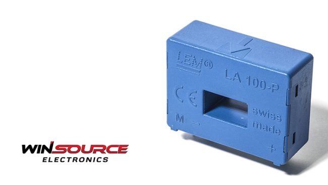
Overview of the LA100-P/SP50 Current Sensor
This closed-loop sensor utilizes the Hall effect and is designed for printed circuit board installation. Its insulated housing is compliant with the UL 94-V0 standard, ensuring safety in various applications.
Electrical Parameters
Primary Side:
- Rated effective value current: 100 A
- Primary current measurement range: 0 .. ± 150 A
- Measure resistance @TA = 70°C: 50 Ohm (min), 42 Ohm (max)
- Measure resistance @TA = 85°C: 22 Ohm (min), 14 Ohm (max)
Secondary Side:
- Rated effective value current: 50 mA
- Conversion rate: 1:2000
- Supply voltage (± 5 %): ± 12 .. 15 V
- Current consumption: 10 mA (@±15V)
General Parameters
- Ambient operating temperature: -40 .. +85 °C
- Ambient storage temperature: -50 .. +95 °C
- Secondary coil resistance @TA = 70°C: 120 Ohm
- Secondary coil resistance @TA = 85°C: 128 Ohm
- Mass: 18 g
- Standard: EN 50178:1997
Installation Steps
Now that we have a good grasp of the LA100-P/SP50’s specifications, let’s move on to the installation process.
Step 1: Gather Your Tools
Ensure you have the necessary tools and equipment for a smooth installation. This includes the LA100-P/SP50 current sensor, a compatible power supply, and any required cables or connectors.
Step 2: Identify the Installation Location
Select a suitable location on the printed circuit board for installing the LA100-P/SP50. Consider factors such as accessibility, proximity to other components, and thermal considerations.
Step 3: Connect Primary and Secondary Sides
Carefully connect the primary and secondary sides of the sensor, ensuring proper alignment and secure connections. Refer to the provided specifications for guidance on the correct wiring configuration.
Step 4: Power Supply Connection
Connect the power supply to the LA100-P/SP50, adhering to the specified voltage range (± 12 .. 15 V). Double-check the polarity to avoid any potential damage.
Step 5: Insulation Testing
Before proceeding further, perform insulation testing by applying a 2.5 kV RMS voltage for AC insulation testing at 50 Hz for one minute. This step ensures the safety and reliability of the installation.
Using the LA100-P/SP50
With the LA100-P/SP50 successfully installed, let’s explore how to make the most of its features in your applications.
Step 6: Calibration
Calibrate the LA100-P/SP50 according to your specific requirements. This may involve adjusting the offset current and ensuring accuracy at the desired operating conditions.
Step 7: Application Considerations
Explore the versatile applications of the LA100-P/SP50, including AC frequency conversion speed regulation, servo motor traction, static conversion of DC motor traction, battery power, uninterruptible power supply (UPS), switching power supply (SMPS), and welding machine power supply.
Step 8: Monitoring and Troubleshooting
Regularly monitor the performance of the LA100-P/SP50 in your system. In case of any issues, refer to the troubleshooting guide provided in the user manual or seek assistance from the manufacturer.
Troubleshooting and Common Issues
As with any technical device, the LA100-P/SP50 current sensor may encounter occasional challenges during installation or use. Understanding common issues and knowing how to troubleshoot them is essential to ensure the sensor performs optimally. In this section, we’ll address some typical problems users might face and provide practical solutions.
1. Incorrect Wiring or Connection Issues
Symptoms: Unexpected readings or no output.
Solution:
- Double-check the wiring according to the specifications provided.
- Ensure a secure connection between the primary and secondary sides.
- Confirm that the power supply is within the specified voltage range.
2. Calibration Difficulties
Symptoms: Inaccurate measurements or difficulty calibrating the sensor.
Solution:
- Follow the calibration instructions in the user manual precisely.
- Verify that the offset current is properly adjusted.
- Check for any external factors affecting the calibration process, such as magnetic interference.
3. Insulation Failures
Symptoms: Issues with insulation testing or safety concerns.
Solution:
- Revisit the insulation testing step, ensuring the applied voltage meets the specified requirements.
- Inspect the sensor for any visible damage to the insulation.
- If problems persist, consult the user manual or contact customer support.
4. Temperature-Related Drift
Symptoms: Offset current drifting with temperature changes.
Solution:
- Verify that the ambient temperature falls within the specified operating range.
- If drift persists, recalibrate the sensor at the operating temperature.
- Consider external factors such as airflow and nearby heat sources that might affect temperature stability.
5. Power Supply Issues
Symptoms: Unstable readings or sensor malfunctions.
Solution:
- Confirm that the power supply voltage remains stable within the specified range.
- Check for loose connections or damaged cables.
- Consider using a regulated power supply for consistent performance.
6. Interference Problems
Symptoms: Inaccuracies caused by external electromagnetic interference.
Solution:
- Identify potential sources of interference and relocate the sensor if possible.
- Use shielding or filters to minimize electromagnetic interference.
- Ensure that the installation location is free from strong magnetic fields.
7. Response Time Concerns
Symptoms: Delayed response time affecting real-time measurements.
Solution:
- Check if the application demands fall within the specified response time of the sensor.
- Optimize the system setup and configuration for faster response.
- Consider adjusting the bandwidth settings if applicable.
8. Unusual Behavior After Overload
Symptoms: Residual current or erratic readings after exceeding the sensor’s maximum limits.
Solution:
- Allow the sensor to reset after an overload event.
- Perform insulation testing again to ensure no damage occurred.
- If issues persist, contact customer support for further assistance.
9. Communication and Integration Problems
Symptoms: Difficulties integrating the sensor into a larger system.
Solution:
- Ensure compatibility with other components in the system.
- Check communication protocols and configurations for consistency.
- Refer to the user manual for any specific integration guidelines.
The LA100-P/SP50 current sensor is an accurate tool for measuring DC, AC, and pulse currents. By following this step-by-step guide, you can confidently install and use the LA100-P/SP50 in various applications, ensuring optimal performance and accurate measurements.
For sourcing the LA100-P/SP50 and other electrical components, consider reputable suppliers like WIN SOURCE. Their extensive catalog and commitment to quality make them a trusted partner for obtaining the tools you need for your electrical projects.
© 2025 Win Source Electronics. All rights reserved. This content is protected by copyright and may not be reproduced, distributed, transmitted, cached or otherwise used, except with the prior written permission of Win Source Electronics.
COMMENTS