* Question
When multiple pins are assigned to the same external interrupt, how does the external interrupt logic behave according to the mode and polarity bits?
* Answer
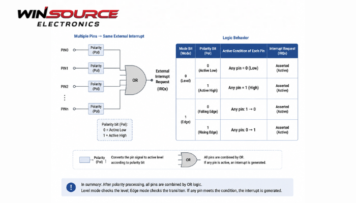
When multiple pins share a single external interrupt line, the behavior is typically controlled by mode bits and polarity bits configured for each pin. The general rules are:
1.Mode Bit (Edge vs. Level):
- Edge-sensitive mode: The interrupt is triggered when the pin changes state (rising edge, falling edge, or both depending on polarity).
- Level-sensitive mode: The interrupt is triggered when the pin is at a specific logic level (high or low) and remains active as long as the level condition persists.
2.Polarity Bit:
Defines which edge or level triggers the interrupt:
- Rising edge / high level → active when the signal transitions from 0 → 1 or stays high.
- Falling edge / low level → active when the signal transitions from 1 → 0 or stays low.
3.Multiple Pins on One Line:
If any pin meets its configured mode/polarity condition, the shared external interrupt is asserted.
- For level-sensitive interrupts, the interrupt remains active until all contributing pins are cleared (no longer meet the active level).
- For edge-sensitive interrupts, each qualifying edge on any pin generates an interrupt event; multiple edges may be latched if the hardware supports it.
4.Logic Implementation:
- The external interrupt controller typically performs a logical OR across all pins mapped to the same interrupt line.
- The combined output respects individual pin configurations for edge/level and polarity.
Summary Table:
Pin Condition | Mode | Polarity | Interrupt Triggered? |
Rising edge | Edge | Rising | Yes |
Falling edge | Edge | Falling | Yes |
High level | Level | High | Yes (remains active until low) |
Low level | Level | Low | Yes (remains active until high) |
Any pin meets condition | Any mode | Any polarity | External interrupt asserted |
COMMENTS