
What kinds of security status are there through secure message transmission?
There are several security measures and statuses associated with secure message transmission. Here are some common ones:
- Encryption: Encryption is a fundamental security measure used to protect the confidentiality of messages. It involves encoding the message using cryptographic algorithms, making it unreadable to anyone who does not possess the decryption key.
- Transport Layer Security (TLS): TLS is a protocol that ensures secure communication over a network. It establishes an encrypted connection between a client and a server, preventing unauthorized access and eavesdropping.
- Secure Sockets Layer (SSL): SSL is the predecessor of TLS, providing secure communication between web browsers and servers. SSL certificates authenticate the identity of the server and enable encryption.
- End-to-End Encryption (E2EE): E2EE ensures that messages are encrypted from the sender to the intended recipient, without intermediaries being able to access the plaintext. Only the sender and recipient possess the encryption keys required to decrypt the messages.
- Forward Secrecy: Forward secrecy, also known as perfect forward secrecy (PFS), ensures that even if an encryption key is compromised in the future, previous communications remain secure. Each session generates a unique key, preventing the exposure of past messages.
- Digital Signatures: Digital signatures verify the authenticity and integrity of a message. They are created using the sender’s private key and can be verified using the corresponding public key, providing assurance that the message has not been tampered with and originated from the claimed sender.
- Two-Factor Authentication (2FA): 2FA adds an additional layer of security by requiring users to provide two different types of authentication factors, typically something they know (like a password) and something they possess (like a physical token or a mobile device).
- Secure Message Protocols: Various protocols, such as Pretty Good Privacy (PGP), Secure/Multipurpose Internet Mail Extensions (S/MIME), and OpenPGP, provide standards for secure message transmission. These protocols incorporate encryption, digital signatures, and other security measures.
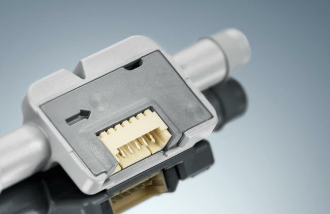
What is the structure of the hot wire air flow sensor?
A hot wire air flow sensor, also known as a mass air flow (MAF) sensor, is a device used in automotive engines to measure the amount of air entering the engine. The structure of a typical hot wire air flow sensor consists of the following components:
- Sensor Element: The sensor element is the main part of the hot wire air flow sensor and is responsible for measuring the airflow. It usually consists of a thin wire made of platinum or another heat-resistant material. The wire is heated to a constant temperature using an electric current.
- Housing: The sensor element is enclosed within a housing, which is typically made of plastic. The housing protects the sensor element from external influences and provides mechanical support.
- Intake Tube: The hot wire air flow sensor is located in the intake tube of the engine, usually positioned between the air filter and the throttle body. The intake tube directs the incoming air toward the sensor element.
- Electronics: The hot wire air flow sensor is connected to the engine control unit (ECU) through electrical wiring. The ECU provides the necessary power to heat the sensor element and receives the signal generated by the sensor to calculate the mass airflow.
Working Principle: The hot wire air flow sensor operates based on the cooling effect of the airflow passing over the heated wire. As the air flows over the wire, it cools down the wire, causing a change in its electrical resistance. The ECU measures the electrical current required to maintain the wire at a constant temperature, which changes as a result of the cooling effect. The change in current is used to determine the mass of the airflow.
The hot wire air flow sensor’s structure and working principle may vary slightly among different manufacturers and models, but the fundamental concept remains the same. It is an essential component in modern engine management systems, helping to optimize fuel injection and ensure proper air-fuel ratio for efficient combustion.
What is the SDA output?
The SDA (Serial Data) output is a signal line in a serial communication protocol called I2C (Inter-Integrated Circuit). I2C is a commonly used bus protocol for communication between integrated circuits on a circuit board.In an I2C system, the SDA line carries bidirectional serial data, meaning it can transmit and receive data. The SDA line is used for transmitting and receiving data between the I2C master device and the I2C slave devices connected on the bus.The SDA line operates using a two-wire interface, which includes the SDA line and the SCL (Serial Clock) line. The SDA line carries the actual data being transmitted or received, while the SCL line provides the clock signal used for synchronizing the data transfer.
The SDA line is typically driven by an open-drain or open-collector output, allowing multiple devices to share the bus and control the SDA line. Each device connected to the bus has a unique address, and the I2C protocol ensures that only the intended recipient receives the data sent on the SDA line.The SDA line’s logic level is determined by the transmitting device, which can drive it either high or low. The receiving device, on the other hand, can only pull the SDA line low or release it, allowing the line to be pulled high by a pull-up resistor.By toggling the SCL line and reading or writing data on the SDA line, devices on the I2C bus can communicate with each other, enabling data transfer and control in various electronic systems and components.
The difference between FET and transistor:
A Field-Effect Transistor (FET) and a transistor are both electronic devices used for amplification and switching purposes, but they have some key differences in terms of structure and operation. Here are the main differences between FETs and transistors:
- Structure: The basic transistor structure consists of three layers of semiconductor material: the emitter, base, and collector. Transistors are typically classified into two main types: bipolar junction transistors (BJTs) and junction field-effect transistors (JFETs). FETs, on the other hand, are majority carrier devices and have a different structure. They are composed of three main regions: the source, gate, and drain. FETs are further categorized into two types: Metal-Oxide-Semiconductor Field-Effect Transistors (MOSFETs) and Junction Field-Effect Transistors (JFETs).
- Operation: The operation of transistors and FETs is based on different principles. Transistors are current-controlled devices, where the base current controls the collector current in BJTs, or the gate current controls the channel between source and drain in JFETs. In contrast, FETs are voltage-controlled devices, meaning the voltage applied to the gate controls the current flow between the source and drain. The gate voltage controls the depletion region’s width or the conductivity of the channel, allowing or blocking current flow.
- Input Impedance: FETs typically have a very high input impedance, making them less susceptible to loading effects from connected circuits. They require very little input current to control the device. Transistors, on the other hand, have lower input impedance, and their operation depends on the current flowing into the base or gate terminal.
- Switching Speed: FETs generally have faster switching speeds compared to transistors. This is because FETs do not have the minority carrier storage and recombination time associated with bipolar transistors. The absence of this inherent capacitance allows FETs to switch on and off more quickly, making them suitable for high-frequency applications.
- Voltage Handling: FETs can typically handle higher voltages compared to transistors. This is due to the absence of current flow through the gate terminal, allowing FETs to have higher breakdown voltage ratings. Transistors, especially BJTs, have limitations on the maximum voltage they can handle.
- Thermal Stability: FETs generally exhibit better thermal stability compared to transistors. This is because FETs are voltage-controlled devices, and their characteristics are less affected by temperature variations compared to transistors.
What addressing methods does the Motorola MC68HC08 series have?
The Motorola MC68HC08 series, also known as the HC08 microcontrollers, supports multiple addressing modes to facilitate accessing memory and peripherals. The specific addressing modes available in the HC08 series are as follows:
- Immediate Addressing: With immediate addressing, the operand or data is directly specified within the instruction itself. It allows immediate data values to be used as operands for arithmetic or logical operations.
- Direct Addressing: Direct addressing mode involves specifying the memory address directly in the instruction. The instruction operates on the data stored at that specific memory location.
- Indexed Addressing: Indexed addressing mode allows addressing memory locations using a base address and an offset. The offset value is added to the base address, and the resulting address is used to access the memory or data.
- Extended Addressing: Extended addressing mode is used when accessing memory locations outside the 64KB address space of the core microcontroller. The instruction specifies a 16-bit address that extends beyond the default address range.
- Relative Addressing: Relative addressing mode is used for branching instructions. It involves specifying a relative offset or displacement from the current program counter (PC) value to determine the target address.
- Indirect Addressing: Indirect addressing allows the use of a memory location as a pointer to another memory location. Instead of directly specifying the address, the instruction uses the content of a memory location as the address.
- Stack Pointer Addressing: Stack pointer addressing is used to push or pop data onto or from the stack. The stack pointer register is used as an implicit operand, and the stack operations are performed relative to its value.
What are the different requirements for electronic equipment under different system operating conditions?
The requirements for electronic equipment can vary depending on the system’s operating conditions. Here are some common factors that may impact the requirements for electronic equipment:
- Temperature: Operating temperature range is a critical consideration for electronic equipment. Some systems operate in extreme temperature environments, such as industrial or automotive applications, where equipment must withstand high or low temperatures without performance degradation or failure. The electronic components and materials used in such equipment should be able to handle the specified temperature range.
- Humidity: High humidity levels can cause condensation, leading to moisture-related issues like corrosion and short circuits. Electronic equipment intended for humid environments, such as outdoor or marine applications, may require additional protection, such as conformal coating, sealed enclosures, or moisture-resistant components.
- Altitude: Operating at high altitudes affects air pressure and can impact the performance of electronic equipment. Systems used in aviation or mountainous regions may require design considerations to ensure proper functioning at varying atmospheric pressures.
- Shock and Vibration: Some applications expose electronic equipment to mechanical shock and vibration, such as in automotive, aerospace, or industrial settings. Equipment intended for these environments needs to be designed to withstand and mitigate the effects of shocks and vibrations to prevent component damage or malfunction.
- EMI/EMC Compliance: Electronic equipment should meet electromagnetic interference (EMI) and electromagnetic compatibility (EMC) requirements. These regulations ensure that the equipment operates reliably in the presence of electromagnetic noise and doesn’t interfere with other devices or systems. Compliance may involve shielding, filtering, grounding, and proper circuit layout techniques.
- Power Supply: Different operating conditions may require specific power supply considerations. For example, equipment used in remote or off-grid locations may require efficient power management or alternative power sources like batteries or solar panels.
- Environmental Factors: Specific industries or applications may have unique environmental requirements. For instance, equipment used in hazardous locations might need to meet specific safety standards, such as explosion-proof or intrinsically safe designs.
- Reliability and Redundancy: Critical systems may demand high reliability and redundancy to minimize the risk of failure. Redundant power supplies, backup systems, fault tolerance, and failure detection mechanisms can be necessary for applications where downtime or system failure is unacceptable.
What is the role of the Receive Buffer (RxB)?
The Receive Buffer (RxB) plays a crucial role in data communication and is typically associated with serial communication interfaces such as UART (Universal Asynchronous Receiver-Transmitter) or USART (Universal Synchronous/Asynchronous Receiver-Transmitter). The RxB is a memory location or a dedicated hardware register that temporarily stores incoming data before it is processed by the receiving device or software. Its primary role is to provide a storage space where received data can be held until it is ready for further processing.
Here are some key aspects of the Receive Buffer’s role:
- Data Reception: When data is received by the communication interface, it is typically transferred into the Receive Buffer. This buffer acts as an intermediate storage location where the received data bytes are stored. The buffer can be a dedicated hardware register or a portion of memory allocated for this purpose.
- Temporary Storage: The Receive Buffer temporarily holds the received data until it can be processed by the receiving device or software. This temporary storage allows the receiving device or software to access the received data at its own pace, preventing data loss due to timing mismatches.
- Data Processing: Once the data is stored in the Receive Buffer, the receiving device or software can read the data from the buffer and process it as required. This processing may involve tasks such as data decoding, error checking, protocol handling, or further application-specific processing.
- Flow Control: In some cases, the Receive Buffer can be used for flow control purposes. Flow control mechanisms help regulate the data flow between the sender and receiver to avoid overwhelming the receiving device with data. The Receive Buffer can be used as part of flow control protocols to manage the rate of incoming data and prevent buffer overflow.
- Interrupt Generation: Many serial communication interfaces generate an interrupt signal when new data arrives and is stored in the Receive Buffer. This interrupt serves as a notification to the system or software that new data is available for processing. The interrupt handler can then respond by reading the data from the Receive Buffer and initiating the necessary actions.
What is an electrolyte solution?
An electrolyte solution is a liquid or solvent that contains ions capable of conducting an electric current. It is formed when certain substances, known as electrolytes, dissolve in a solvent, typically water. Electrolyte solutions play a crucial role in various fields, including chemistry, biology, and electrochemistry.
Here are some key characteristics and properties of electrolyte solutions:
- Dissolved Ions: Electrolyte solutions consist of ions, which are electrically charged particles. These ions can be either positively charged (cations) or negatively charged (anions). Common electrolytes include salts, acids, and bases.
- Conductivity: One of the defining properties of electrolyte solutions is their ability to conduct electricity. The dissolved ions in the solution can move freely and carry an electric charge, allowing for the flow of electric current.
- Ionization/Dissociation: Electrolyte compounds in a solvent undergo ionization or dissociation, which means they break apart into individual ions. For example, when table salt (sodium chloride, NaCl) dissolves in water, it dissociates into sodium ions (Na+) and chloride ions (Cl-).
- Ion Mobility: In an electrolyte solution, ions are mobile and can move freely within the solution under the influence of an electric field. The mobility of ions contributes to the conductivity of the solution.
- Concentration: The concentration of electrolytes in a solution affects its conductivity. Higher concentrations of dissolved electrolytes typically result in greater conductivity, as there are more ions available for charge transport.
- pH and Acidity: Some electrolyte solutions, such as acids and bases, can influence the pH of a solution. Acids release hydrogen ions (H+) into the solution, making it acidic, while bases release hydroxide ions (OH-) and increase the alkalinity.
- Electrochemical Reactions: Electrolyte solutions are essential in electrochemical processes, such as electrolysis and batteries. These solutions facilitate the movement of ions, allowing for the transfer of electrons during redox reactions.
What is a front impact sensor?
A front impact sensor, also known as a frontal crash sensor or front accelerometer, is a component used in automotive safety systems to detect and measure the severity of a frontal impact or collision. It is typically located in the front portion of a vehicle, such as the front bumper or the engine compartment.
The primary function of a front impact sensor is to provide input to the vehicle’s airbag control module (also known as the airbag control unit or crash sensor module) in the event of a frontal collision. The sensor detects the sudden changes in acceleration or deceleration that occur during a crash and sends a signal to the airbag control module to deploy the appropriate airbags and initiate other safety measures.
Here are some key aspects and features of front impact sensors:
- Acceleration Measurement: Front impact sensors are designed to measure the acceleration forces experienced by the vehicle during a collision. They typically use accelerometers, which are electronic sensors capable of detecting changes in acceleration along specific axes.
- Threshold Detection: Front impact sensors are calibrated to activate and trigger the airbag system when the measured acceleration exceeds a predetermined threshold. The threshold is typically set to detect significant impacts that pose a risk to the occupants.
- Collision Severity Assessment: By measuring the acceleration forces, front impact sensors can help assess the severity of a collision. This information is used by the airbag control module to determine the appropriate deployment strategy for the airbags, including the number of airbags to deploy, the deployment timing, and the inflation level.
- Multiple Sensors: Some vehicles may have multiple front impact sensors strategically placed at different locations to improve accuracy and reliability in detecting and assessing frontal impacts. Multiple sensors provide redundancy and enhance the system’s ability to detect collisions from different angles.
- Integration with Safety Systems: Front impact sensors are part of the overall vehicle safety system, working in conjunction with other components such as airbags, seat belt pretensioners, and crash sensors in different parts of the vehicle. They collaborate to provide a comprehensive safety response in the event of a collision.
What is the basic structure of the FPGA?
The basic structure of a Field-Programmable Gate Array (FPGA) consists of three key components: programmable logic blocks (PLBs), programmable interconnects, and input/output (I/O) blocks. These components work together to provide the flexibility and reconfigurability that define an FPGA.
- Programmable Logic Blocks (PLBs): PLBs are the fundamental building blocks of an FPGA. They are composed of configurable logic elements (LEs) that can be programmed to implement different digital logic functions. LEs typically consist of look-up tables (LUTs) that can be programmed to store truth tables, flip-flops for sequential logic, and multiplexers for routing signals. PLBs can be interconnected and configured to perform complex combinational and sequential logic operations.
- Programmable Interconnects: The programmable interconnects provide the routing resources that connect the PLBs and I/O blocks within the FPGA. These interconnects consist of a network of configurable switches and routing channels. The switches can be dynamically programmed to establish connections between various PLBs and I/O blocks, allowing for the creation of specific signal paths based on the desired circuit functionality.
- Input/Output (I/O) Blocks: I/O blocks act as the interface between the FPGA and external devices or systems. They provide the connections for input and output signals, which can include digital signals, analog signals, or specialized interfaces like high-speed serial transceivers. I/O blocks often include features such as voltage level shifters, input/output buffers, and programmable input/output standards to accommodate different signal types and voltage levels.
COMMENTS